Time constant circuits
Question 1:
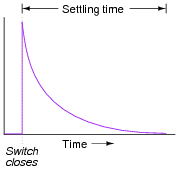
Generally speaking, how many "time constants" worth of time does it take for the voltage and current to ßettle" into their final values in an RC or LR circuit, from the time the switch is closed?
|
|
However, after 5 time constants' worth of time, the variables in an RC or LR circuit will have settled to within 0.6% of their final values, which is good enough for most people to call "final."
Notes:
The stock answer of "5 time constants" as the amount of time elapsed between the transient event and the "final" settling of voltage and current values is widespread, but largely misunderstood. I've encountered more than a few graduates of electronics programs who actually believe there is something special about the number 5, as though everything grinds to a halt at exactly 5 time constants worth of time after the switch closes.
In reality, the rule of thumb of "5 time constants" as a settling time in RC and LR circuits is an approximation only. Somewhere I recall reading an old textbook that specified ten time constants as the time required for all the variables to reach their final values. Another old book declared seven time constants. I think we're getting impatient as the years roll on!
Question 2:
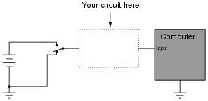
Suppose a fellow electronics technician approaches you with a design problem. He needs a simple circuit that outputs brief pulses of voltage every time a switch is actuated, so that a computer receives a single pulse signal every time the switch is actuated, rather than a continuous ön" signal for as long as the switch is actuated:
|
|
The technician suggests you build a passive differentiator circuit for his application. You have never heard of this circuit before, but you probably know where you can research to find out what it is! He tells you it is perfectly okay if the circuit generates negative voltage pulses when the switch is de-actuated: all he cares about is a single positive voltage pulse to the computer each time the switch actuates. Also, the pulse needs to be very short: no longer than 2 milliseconds in duration.
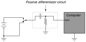
Given this information, draw a schematic diagram for a practical passive differentiator circuit within the dotted lines, complete with component values.
|
|
Did you really think I would give you the component values, too? I can't make it too easy for you!
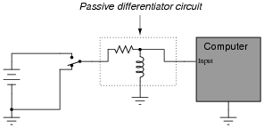
Challenge question: An alternative design to the differentiator circuit shown above is this:
|
|
This circuit would certainly work to create brief pulses of voltage to the computer input, but it would also likely destroy the computer's input circuitry after a few switch actuations! Explain why.
Notes:
The behavior of a differentiator circuit may be confusing to students with exposure to calculus, because the output of such a circuit is not strictly related to the rate of change of the input voltage over time. However, if the time constant of the circuit is short in comparison to the period of the input signal, the result is close enough for many applications.
Question 3:
When a circuit designer needs a circuit to provide a time delay, he or she almost always chooses an RC circuit instead of an LR circuit. Explain why this is.
Notes:
The answer given here is purposely minimal. You should ask your students to give responses more thoughtful than this! Ask them why capacitors are cheaper than inductors. Ask them to explain what is meant by ëasier to work with," in technical terms.
Question 4:
| Don't just sit there! Build something!! |
Learning to mathematically analyze circuits requires much study and practice. Typically, students practice by working through lots of sample problems and checking their answers against those provided by the textbook or the instructor. While this is good, there is a much better way.
You will learn much more by actually building and analyzing real circuits, letting your test equipment provide the änswers" instead of a book or another person. For successful circuit-building exercises, follow these steps:
- 1.
- Carefully measure and record all component values prior to circuit construction.
- 2.
- Draw the schematic diagram for the circuit to be analyzed.
- 3.
- Carefully build this circuit on a breadboard or other convenient medium.
- 4.
- Check the accuracy of the circuit's construction, following each wire to each connection point, and verifying these elements one-by-one on the diagram.
- 5.
- Mathematically analyze the circuit, solving for all values of voltage, current, etc.
- 6.
- Carefully measure those quantities, to verify the accuracy of your analysis.
- 7.
- If there are any substantial errors (greater than a few percent), carefully check your circuit's construction against the diagram, then carefully re-calculate the values and re-measure.
Avoid very high and very low resistor values, to avoid measurement errors caused by meter "loading". I recommend resistors between 1 kW and 100 kW, unless, of course, the purpose of the circuit is to illustrate the effects of meter loading!
One way you can save time and reduce the possibility of error is to begin with a very simple circuit and incrementally add components to increase its complexity after each analysis, rather than building a whole new circuit for each practice problem. Another time-saving technique is to re-use the same components in a variety of different circuit configurations. This way, you won't have to measure any component's value more than once.
Notes:
It has been my experience that students require much practice with circuit analysis to become proficient. To this end, instructors usually provide their students with lots of practice problems to work through, and provide answers for students to check their work against. While this approach makes students proficient in circuit theory, it fails to fully educate them.
Students don't just need mathematical practice. They also need real, hands-on practice building circuits and using test equipment. So, I suggest the following alternative approach: students should build their own "practice problems" with real components, and try to mathematically predict the various voltage and current values. This way, the mathematical theory "comes alive," and students gain practical proficiency they wouldn't gain merely by solving equations.
Another reason for following this method of practice is to teach students scientific method: the process of testing a hypothesis (in this case, mathematical predictions) by performing a real experiment. Students will also develop real troubleshooting skills as they occasionally make circuit construction errors.
Spend a few moments of time with your class to review some of the "rules" for building circuits before they begin. Discuss these issues with your students in the same Socratic manner you would normally discuss the worksheet questions, rather than simply telling them what they should and should not do. I never cease to be amazed at how poorly students grasp instructions when presented in a typical lecture (instructor monologue) format!
A note to those instructors who may complain about the "wasted" time required to have students build real circuits instead of just mathematically analyzing theoretical circuits:
What is the purpose of students taking your course?
If your students will be working with real circuits, then they should learn on real circuits whenever possible. If your goal is to educate theoretical physicists, then stick with abstract analysis, by all means! But most of us plan for our students to do something in the real world with the education we give them. The "wasted" time spent building real circuits will pay huge dividends when it comes time for them to apply their knowledge to practical problems.
Furthermore, having students build their own practice problems teaches them how to perform primary research, thus empowering them to continue their electrical/electronics education autonomously.
In most sciences, realistic experiments are much more difficult and expensive to set up than electrical circuits. Nuclear physics, biology, geology, and chemistry professors would just love to be able to have their students apply advanced mathematics to real experiments posing no safety hazard and costing less than a textbook. They can't, but you can. Exploit the convenience inherent to your science, and get those students of yours practicing their math on lots of real circuits!
Question 5:
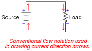
Capacitors and inductors alike have the ability to both store and release energy. This makes them more complicated than resistors, which merely dissipate energy. As a consequence, the relationship between direction of current and polarity of voltage is a bit more complex for capacitors and inductors than it is for power sources and resistors:
|
|
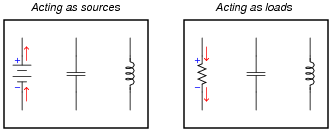
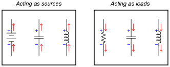
Draw current arrows and voltage polarity marks (+ and - symbols) next to each of the following components, the left group representing a battery, capacitor, and inductor all acting as energy sources and the right group representing a resistor, capacitor, and inductor all acting as energy loads:
|
|
|
|
Follow-up question: what form does the stored energy take inside each type of reactive component? In other words, how does an inductor store energy, and how does a capacitor store energy?
Notes:
Although the answer may seem a bit too easy - nay, even obvious - the point here is to get students to correlate the behavior of capacitors and inductors in terms of components they already understand very well. Then, they may correctly associate direction of current with polarity of voltage drop according to the direction of energy flow (source versus load) the reactive component is subjected to.
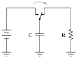
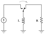
Question 6:
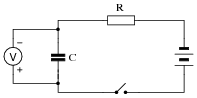
Suppose this circuit were constructed, using a fully discharged capacitor (0 volts) and a voltmeter connected in parallel with it to measure its voltage:
|
|
What will happen to the capacitor's voltage after the switch is closed? Be as precise as you can with your answer, and explain why it does what it does.
Notes:
A qualitative analysis of this circuit's behavior may be performed without using any calculus, or even algebra. Ask students to explain what happens to current in the circuit as the capacitor's voltage begins to increase, and then what effect that has on the rate of voltage rise, and so on, graphing the results for all too see.
Hint: the rate of voltage rise across a capacitor is in direct proportion to the quantity of current going "through" the capacitor.
Question 7:
Suppose this circuit were constructed, using an inductor and an ammeter connected in series with it to measure its current:
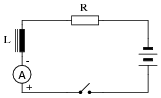
|
|
What will happen to the inductor's current after the switch is closed? Be as precise as you can with your answer, and explain why it does what it does.
Notes:
A qualitative analysis of this circuit's behavior may be performed without using any calculus, or even algebra. Ask students to explain what happens to the voltage across the inductor as the circuit current beings to increase, and what effect that has on the rate of current rise, and so on, graphing the results for all too see.
Hint: the rate of current rise through an inductor is in direct proportion to the quantity of voltage dropped across the inductor.
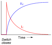
Question 8:
Graph both the capacitor voltage (EC) and the capacitor current (IC) over time as the switch is closed in this circuit. Assume the capacitor begins in a complete uncharged state (0 volts):

|
|
|
|
Notes:
Have your students explain why the voltage and current curves are shaped as they are.
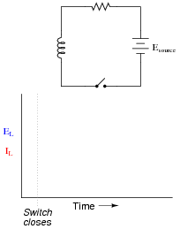
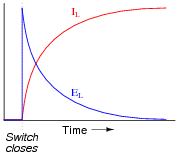
Question 9:
Graph both the inductor voltage (EL) and the inductor current (IL) over time as the switch is closed in this circuit:
|
|
|
|
Notes:
Have your students explain why the voltage and current curves are shaped as they are.
Question 10:
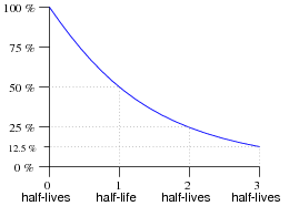
There are many, many processes in the natural sciences where variables either grow (become larger) or decay (become smaller) over time. Often, the rate at which these processes grow or decay is directly proportional to the growing or decaying quantity. Radioactive decay is one example, where the rate of decay of a radioactive substance is proportional to the quantity of that substance remaining. The growth of small bacterial cultures is another example, where the growth rate is proportional to the number of live cells.
In processes where the rate of decay is proportional to the decaying quantity (such as in radioactive decay), a convenient way of expressing this decay rate is in terms of time: how long it takes for a certain percentage of decay to occur. With radioactive substances, the decay rate is commonly expressed as half-life: the time it takes for exactly half of the substance to decay:
|
|
In RC and LR circuits, decay time is expressed in a slightly different way. Instead of measuring decay rate in units of half-lives, we measure decay rate in units of time constants, symbolized by the Greek letter "tau" (t).
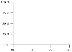
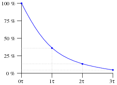
What is the percentage of decay that takes place in an RC or LR circuit after one "time constant's" worth of time, and how is this percentage value calculated? Note: it is not 50%, as it is for "half life," but rather a different percentage figure.
Graph the curve of this decay, plotting points at 0, 1, 2, and 3 time constants:
|
|
|
|
Notes:
I like to use the example of radioactive decay to introduce time constants, because it seems most people have at least heard of something called "half-life," even if they don't know exactly what it is.
Incidentally, the choice to measure decay in either "half lives" or "time constants" is arbitrary. The curve for radioactive decay is the exact same curve as that of an RC or LR discharge process, and is characterized by the same differential equation:
|
Where,
Q = Decaying variable (grams of substance, volts, amps, whatever)
k = Relative decay rate
t = Time
By solving this separable differential equation, we naturally arrive at an equation expressing Q in terms of an exponential function of e:
|
Thus, it makes more sense to work with units of "time constants" based on e than with "half lives," although admittedly "half-life" is a concept that makes more intuitive sense. Incidentally, 1 half-life is equal to 0.693 time constants, and 1 time constant is equal to 1.443 half-lives.
Question 11:
|
�f(x) dx Calculus alert! |
|
|
Would a larger capacitance value result in a slower discharge, or a faster discharge? How about a larger resistance value? You may find the Öhm's Law" equation for capacitance helpful in answering both these questions:
|
Now consider an inductor, "charged" by a current source and then switched to a resistor for discharging:
|
|
Would a larger inductance value result in a slower discharge, or a faster discharge? How about a larger resistance value? You may find the Öhm's Law" equation for inductance helpful in answering both these questions:
|
- �
- Larger capacitance = slower discharge
- �
- Larger resistance = slower discharge
- �
- Larger inductance = slower discharge
- �
- Larger resistance = faster discharge
Notes:
Students usually want to just use the t = RC and t = L/R formulae to answer questions like this, but unfortunately this does not lend itself to a firm conceptual understanding of time-constant circuit behavior.
If students need hints on how to answer the capacitance and inductance questions, ask them what the fundamental definitions of "capacitance" and ïnductance" are (the ability to store energy . . .). Then ask them what takes longer to discharge (given the same power, or rate of energy release per unit time), a large reservoir of energy or a small reservoir of energy.
If students need hints on how to answer the resistance questions, ask them what each type of reactive component resists change in (voltage for capacitors and current for inductors). Then ask them what condition(s) are necessary to cause the most rapid change in those variables (high current for capacitors and high voltage for inductors). This is most evident by inspection of the differential equations i = C[dv/dt] and v = L [di/dt].
Question 12:
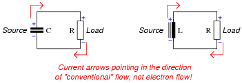
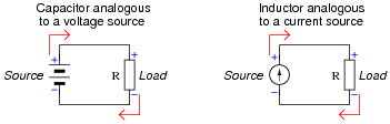
Capacitors tend to oppose change in voltage, and so they may be considered "temporary voltage sources." That is, they tend to hold a constant voltage over time, but they cannot do so indefinitely. Any motion of charge (current) will change the voltage of a capacitor.
Likewise, inductors may be considered "temporary current sources" because while they tend to hold current constant over time, they cannot do so indefinitely. Any application of voltage across a (perfect) inductor will alter the amount of current going through it.
Given the above characterizations, determine what resistance levels will result in the fastest discharge of energy for both the capacitive circuit and the inductive circuit. Considering each of the reactive components (C and L, respectively) as "temporary" power sources whose store of energy will drain over time, determine what value of R in each circuit will result in the quickest depletion of energy by making each source "work hardest:"
|
|
Based on your answer to this question, explain how circuit resistance (R) affects the time constants (t) of RC and of LR circuits.
|
|
Large R values slow down RC circuits and speed up LR circuits, while small R values speed up RC circuits and slow down LR circuits.
Notes:
The leap I expect students to make here is to think about the exchange of energy for both capacitors and inductors as they deliver power to a resistive load. Which ever values of R make the respective sources work the hardest (dissipate the most power at the load) will be the values that make the reactive components discharge quickest.
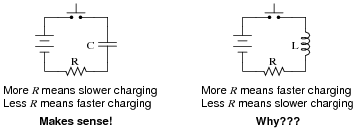
Question 13:
While many students find it easy to understand how the value of R affects the time constant of a resistor-capacitor charging circuit (more R means slower charging; less R means faster charging), the opposite behavior of resistor-inductor circuits (less R means slower charging; more R means faster charging) seems incomprehensible:
|
|
Resistor-capacitor circuit charging behavior probably makes more sense to students because they realize resistance controls charging current, which in turn directly effects how quickly the capacitor's voltage may rise:
|
Current (i) is proportional to the rate of change of voltage ([dv/dt]). Since current is inversely proportional to resistance in a circuit powered by a voltage source, so must be the capacitor charging rate.
One way to help make the inductor charging circuit more sensible is to replace the series voltage-source/resistor combination with its Norton equivalent, a parallel current-source/resistor combination:
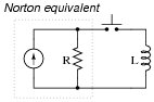
|
|
Re-analyze the circuit in this form, and try to explain why more resistance makes the inductor charging time faster and less resistance makes the inductor charging time slower.
|
The inductor's "charge" is a direct function of current, the change of which (rate of charge) is directly proportional to the amount of voltage impressed across the inductor. In a Norton equivalent circuit, the output voltage is directly proportional to the internal resistance. So, a greater resistance results in a faster charging time.
Notes:
My answer could stand to be a little more detailed, but the main idea here is to have students piece together their own argument explaining why inductor charging rate is directly proportional to resistance. Of course, this is yet another example of the usefulness of Thévenin/Norton equivalent circuits. Sometimes a simple source conversion from one form to the other is all that is needed to achieve a conceptual breakthrough!
Question 14:
What value of resistor would need to be connected in series with a 33 mF capacitor in order to provide a time constant (t) of 10 seconds? Express your answer in the form of a five-band precision resistor color code (with a tolerance of +/- 0.1%).
Notes:
In order for students to answer this question, they must research the RC time constant equation and review the 5-band resistor color code.
Question 15:
What value of resistor would need to be connected in series with a 75 mH inductor in order to provide a time constant (t) of 20 microseconds? Express your answer in the form of a five-band precision resistor color code (with a tolerance of +/- 0.25%).
Notes:
In order for students to answer this question, they must research the LR time constant equation and review the 5-band resistor color code.
Question 16:
An electronic service technician prepares to work on a high-voltage power supply circuit containing one large capacitor. On the side of this capacitor are the following specifications:
|
Obviously this device poses a certain amount of danger, even with the AC line power secured (lock-out/tag-out). Discharging this capacitor by directly shorting its terminals with a screwdriver or some other piece of metal might be dangerous due to the quantity of the stored charge. What needs to be done is to discharge this capacitor at a modest rate.
The technician realizes that she can discharge the capacitor at any rate desired by connecting a resistor in parallel with it (holding the resistor with electrically-insulated pliers, of course, to avoid having to touch either terminal). What size resistor should she use, if she wants to discharge the capacitor to less than 1% charge in 15 seconds? State your answer using the standard 4-band resistor color code (tolerance = +/- 10%).
Notes:
In order to answer this question, students must not only be able to calculate time constants for a simple RC circuit, but they must also remember the resistor color code so as to choose the right size based on color. A very practical problem, and important for safety reasons too!
Question 17:
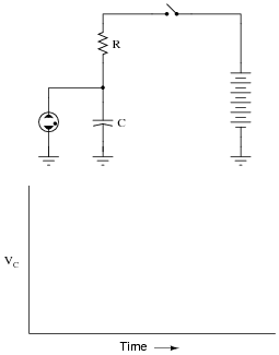
The circuit shown here is called a relaxation oscillator. It works on the principles of capacitor charging over time (an RC circuit), and of the hysteresis of a gas-discharge bulb: the fact that the voltage required to initiate conduction through the bulb is significantly greater than the voltage below which the bulb ceases to conduct current.
In this circuit, the neon bulb ionizes at a voltage of 70 volts, and stops conducting when the voltage falls below 30 volts:
|
|
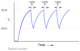
Graph the capacitor's voltage over time as this circuit is energized by the DC source. Note on your graph at what times the neon bulb is lit:
|
|
Follow-up question: assuming a source voltage of 100 volts, a resistor value of 27 kW, and a capacitor value of 22 mF, calculate the amount of time it takes for the capacitor to charge from 30 volts to 70 volts (assuming the neon bulb draws negligible current during the charging phase).
Notes:
What we have here is a very simple strobe light circuit. This circuit may be constructed in the classroom with minimal safety hazard if the DC voltage source is a hand-crank generator instead of a battery bank or line-powered supply. I've demonstrated this in my own classroom before, using a hand-crank "Megger" (high-range, high-voltage ohmmeter) as the power source.
Question 18:
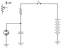
Replace the fixed-value resistor with a potentiometer to adjust the blinking rate of the neon lamp, in this relaxation oscillator circuit. Connect the potentiometer in such a way that clockwise rotation of the knob makes the lamp blink faster:
|
|
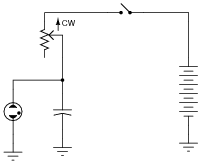
|
|
Notes:
Ask your students to explain why the potentiometer has the speed-changing effect it does on the circuit's flash rate. Would there be any other way to change this circuit's flash rate, without using a potentiometer?
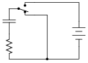
Question 19:
Design a circuit with a three-position switch, where one position charges a capacitor, one position holds the capacitor's voltage constant, and the last position discharges the capacitor. Provide independent, variable adjustments for charging and discharging time constants.
|
|
Notes:
This is an interesting question, as the students are challenged with the design of a circuit, and that the example circuit shown in the answer does not completely fulfill the specified criteria. In order for a student to derive a circuit from the one given in the answer, they must first assess that circuit's operation, to determine what it can and cannot do.
Note that it will not suffice to merely replace the fixed-value resistor with a variable resistor, as this would not provide independent adjustment of charging and discharging time constants.
Question 20:
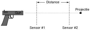
An intervalometer is a device that measures the interval of time between two events. Such devices are commonly used to measure the speed of projectiles, given a known distance between two sensors:
|
|
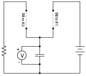
A crude intervalometer may be constructed using two thin wires as sensors, which are broken by the passage of the projectile. The two wires are connected in an RC circuit as such:
|
|
In order for this circuit to function properly as an intervalometer, which wire does the projectile need to break first? Explain why. Also, the voltmeter used in this instrument must be one with as high an input resistance as possible for best accuracy. Explain why this is necessary as well.
Which will produce a greater voltage indication after the test, a fast projectile or a slow projectile? Explain your answer.
Notes:
This is an interesting question because it requires the students to reason through the function of a practical measuring circuit. Not only must students grasp the charge/discharge behavior of a capacitor, but they also must relate it to the practical purpose of the intervalometer, recognizing the importance of voltmeter characteristics as well. Expect substantial discussion on this question.
Question 21:
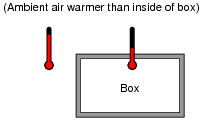
Suppose we were measuring the interior temperature of an insulated box recently removed from a refrigerator, as it was being warmed by the ambient air around it:
|
|
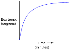
Graphing the box's temperature over time, we see a curve that looks something like this:
|
|
An engineer approaches you and says she wants you to build an electrical circuit that models this thermal system. What kind of circuit would you consider building for the engineer, to make a realistic electrical analogue of the box's temperature? Be as specific as you can in your answer.
I won't show you a schematic diagram for the correct circuit, but I will give you several hints:
- �
- The circuit uses a capacitor and a resistor.
- �
- It is sometimes referred to as a passive integrator circuit.
- �
- Engineers sometimes refer to it as a first-order lag network.
- �
- You've seen this circuit before, just not in the context of modeling a physical process!
Notes:
I like to show this question to beginning students because it shows them an aspect of electrical circuits that they probably never thought to consider: that the behavior of a circuit might mimic the behavior of some other type of physical system or process, and that this principle might be exploited as a modeling tool for engineers. Before the advent of inexpensive digital computers, the analog computer was the simulation tool of choice among engineers of all persuasions. Using resistors, capacitors, and amplifier circuits, these marvelous machines modeled all kinds of physical systems, as electrical constructs of mathematical equations.
But even without knowing anything about calculus, amplifier circuits, or any advanced electronic concepts, beginning students should be able to understand the principle at work in this question.
Question 22:
Electromechanical relays are extremely useful devices, but they have their idiosyncrasies. One of them is a consequence of the fact that the relay's coil acts as an inductor, storing energy in its magnetic field.
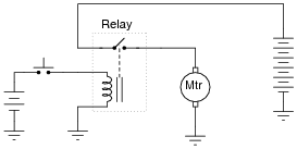
In the following circuit, a relay is used to switch power to a large electric motor, while being controlled by a light-duty pushbutton switch:
|
|
The problem here is every time the pushbutton switch is released, the contacts arc significantly. This happens because the inductor releases all of its stored energy as a high-voltage spark across the opening contacts. Inductive kickback is the phrase commonly used to describe this effect, and over time it will prematurely destroy the switch.
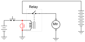
An electronics technician understands the nature of the problem and proposes a solution. By connecting a light bulb in parallel with the relay coil, the coil's energy now has a safer place to dissipate whenever the pushbutton switch contacts open:
|
|
Instead of that stored energy manifesting itself as a high-voltage arc at the switch, it powers the light bulb for a brief time after the switch opens, dissipating in a non-destructive manner.
However, the addition of the light bulb introduces a new, unexpected problem to the circuit. Now, when the pushbutton switch is released, the relay delays for a fraction of a second before disengaging. This causes the motor to övershoot" its position instead of stopping when it is supposed to.
Explain why this happens, with reference to the LR time constant of this circuit before and after the addition of the lamp.
Notes:
This answer is rather minimal, if not obvious. Of course, if the relay takes longer to de-energize, and we were told this has something to do with time constants, then the time constant of the circuit must have increased. What is not so obvious is why t increased. Discuss this with your students, and see what conclusions they reached.
Question 23:
An electrical testing laboratory has designed and built a high-current ßurge" power supply for testing the effects of large electrical currents on certain types of components. The basic idea is that a bank of capacitors are charged to a high voltage by a DC power source (through a current-limiting resistor to protect the power source from overcurrent damage), then quickly discharged through a switch to the test load:
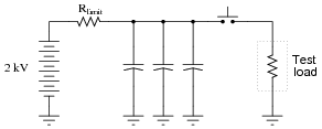
|
|
Due to the magnitude of the transient currents generated by the discharging capacitors, a mechanical switch (as suggested by the pushbutton symbol) is impractical. Instead, an air gap switch is constructed from two metal balls with a needle-point ïonizer" electrode between them. The ionizer electrode connects to a simple inductor/switch circuit that generates a high-voltage pulse sufficient to create a spark. The ionized air created in the spark provides a low-resistance path through the air which the 2000 volts from the capacitor bank can now traverse, thus completing the circuit for surge current between the capacitors and the test load:
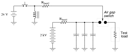
|
|
Suppose this surge power supply circuit failed to work after several months of good service. Nothing happens any more when the pushbutton switch is pressed and released. No spark is heard or seen in the air gap, and the test load receives no surge of current.
A voltmeter placed (carefully!) in parallel with the capacitor bank indicates a full charge voltage of 2035 volts, which is within normal parameters. Based on this information, identify these things:
- �
-
Two components in the circuit that you know must be in good working condition.
- �
- Two components in the circuit that could possibly be bad, and the mode of their failure (either open or shorted).
- �
- Rlimit2 failed open
- �
- Inductor failed open or shorted
- �
- Pushbutton switch failed open or shorted
- �
- 24 VDC supply failed
- �
- Air gap switch ïonizing" needle tip burnt or otherwise worn
Follow-up question: explain how one would safely continue diagnostic measurements in a circuit such as this where there is much potential for electric shock and other hazards.
Notes:
In addition to introducing the concept of an air gap switch and the notion of a ßurge" power supply, this question challenges students to envision practical problems and their respective diagnostic techniques.
It goes without saying that a circuit such as this is very dangerous, and its construction should not be attempted by anyone lacking a thorough understanding of its relevant hazards. Having said that, I will admit to having built one myself, simply to test the validity of an air gap switch for high-voltage, high-current, transient switching. Yes, the concept does work!