Time constant calculations
Question 1:
| Don't just sit there! Build something!! |
Learning to mathematically analyze circuits requires much study and practice. Typically, students practice by working through lots of sample problems and checking their answers against those provided by the textbook or the instructor. While this is good, there is a much better way.
You will learn much more by actually building and analyzing real circuits, letting your test equipment provide the änswers" instead of a book or another person. For successful circuit-building exercises, follow these steps:
- 1.
- Carefully measure and record all component values prior to circuit construction.
- 2.
- Draw the schematic diagram for the circuit to be analyzed.
- 3.
- Carefully build this circuit on a breadboard or other convenient medium.
- 4.
- Check the accuracy of the circuit's construction, following each wire to each connection point, and verifying these elements one-by-one on the diagram.
- 5.
- Mathematically analyze the circuit, solving for all values of voltage, current, etc.
- 6.
- Carefully measure those quantities, to verify the accuracy of your analysis.
- 7.
- If there are any substantial errors (greater than a few percent), carefully check your circuit's construction against the diagram, then carefully re-calculate the values and re-measure.
Avoid very high and very low resistor values, to avoid measurement errors caused by meter "loading". I recommend resistors between 1 kW and 100 kW, unless, of course, the purpose of the circuit is to illustrate the effects of meter loading!
One way you can save time and reduce the possibility of error is to begin with a very simple circuit and incrementally add components to increase its complexity after each analysis, rather than building a whole new circuit for each practice problem. Another time-saving technique is to re-use the same components in a variety of different circuit configurations. This way, you won't have to measure any component's value more than once.
Notes:
It has been my experience that students require much practice with circuit analysis to become proficient. To this end, instructors usually provide their students with lots of practice problems to work through, and provide answers for students to check their work against. While this approach makes students proficient in circuit theory, it fails to fully educate them.
Students don't just need mathematical practice. They also need real, hands-on practice building circuits and using test equipment. So, I suggest the following alternative approach: students should build their own "practice problems" with real components, and try to mathematically predict the various voltage and current values. This way, the mathematical theory "comes alive," and students gain practical proficiency they wouldn't gain merely by solving equations.
Another reason for following this method of practice is to teach students scientific method: the process of testing a hypothesis (in this case, mathematical predictions) by performing a real experiment. Students will also develop real troubleshooting skills as they occasionally make circuit construction errors.
Spend a few moments of time with your class to review some of the "rules" for building circuits before they begin. Discuss these issues with your students in the same Socratic manner you would normally discuss the worksheet questions, rather than simply telling them what they should and should not do. I never cease to be amazed at how poorly students grasp instructions when presented in a typical lecture (instructor monologue) format!
A note to those instructors who may complain about the "wasted" time required to have students build real circuits instead of just mathematically analyzing theoretical circuits:
What is the purpose of students taking your course?
If your students will be working with real circuits, then they should learn on real circuits whenever possible. If your goal is to educate theoretical physicists, then stick with abstract analysis, by all means! But most of us plan for our students to do something in the real world with the education we give them. The "wasted" time spent building real circuits will pay huge dividends when it comes time for them to apply their knowledge to practical problems.
Furthermore, having students build their own practice problems teaches them how to perform primary research, thus empowering them to continue their electrical/electronics education autonomously.
In most sciences, realistic experiments are much more difficult and expensive to set up than electrical circuits. Nuclear physics, biology, geology, and chemistry professors would just love to be able to have their students apply advanced mathematics to real experiments posing no safety hazard and costing less than a textbook. They can't, but you can. Exploit the convenience inherent to your science, and get those students of yours practicing their math on lots of real circuits!
Question 2:
The decay of a variable over time in an RC or LR circuit follows this mathematical expression:
|
Where,
e = Euler's constant ( � 2.718281828)
t = Time, in seconds
t = Time constant of circuit, in seconds
For example, if we were to evaluate this expression and arrive at a value of 0.398, we would know the variable in question has decayed from 100% to 39.8% over the period of time specified.
However, calculating the amount of time it takes for a decaying variable to reach a specified percentage is more difficult. We would have to manipulate the equation to solve for t, which is part of an exponent.
Show how the following equation could be algebraically manipulated to solve for t, where x is the number between 0 and 1 (inclusive) representing the percentage of original value for the variable in question:
|
Note: the "trick" here is how to isolate the exponent [(-t)/(t)]. You will have to use the natural logarithm function!
|
|
|
|
Notes:
In my experience, most American high school graduates are extremely weak in logarithms. Apparently this is not taught very well at the high school level, which is a shame because logarithms are a powerful mathematical tool. You may find it necessary to explain to your students what a logarithm is, and exactly why it ün-does" the exponent.
When forced to give a quick presentation on logarithms, I usually start with a generic definition:
|
|
Verbally defined, the logarithm function asks us to find the power (a) of the base (b) that will yield c.
Next, I introduce the common logarithm. This, of course, is a logarithm with a base of 10. A few quick calculator exercises help students grasp what the common logarithm function is all about:
|
|
|
|
|
|
|
|
After this, I introduce the natural logarithm: a logarithm with a base of e (Euler's constant):
|
Have your students do this simple calculation on their calculators, and explain the result:
|
Next comes an exercise to help them understand how logarithms can ündo" exponentiation. Have your students calculate the following values:
|
|
|
Now, have them take the natural logarithms of each of those answers. They will find that they arrive at the original exponent values (2, 3, and 4, respectively). Write this relationship on the board as such for your students to view:
|
|
|
Ask your students to express this relationship in general form, using the variable x for the power instead of an actual number:
|
It should now be apparent that the natural logarithm function has the ability to ündo" a power of e. Now it should be clear to your students why the given sequence of algebraic manipulations in the answer for this question is true.
Question 3:
Re-write this mathematical expression so that the exponent term (-x) is no longer negative:
|
Also, describe the calculator keystroke sequence you would have to go through to evaluate this expression given any particular value for x.
|
Notes:
I am usually not a fan of discussing calculator keystroke sequences to college-level students, but I have resorted to this at the college where I teach because so many of my students have no idea of how to evaluate exponential expressions! Of course, the actual keystrokes one must push to evaluate this expression depend on the brand of calculator used.
Question 4:
At a party, you happen to notice a mathematician taking notes while looking over the food table where several pizzas are set. Walking up to her, you ask what she is doing. Ï'm mathematically modeling the consumption of pizza," she tells you. Before you have the chance to ask another question, she sets her notepad down on the table and excuses herself to go use the bathroom.
Looking at the notepad, you see the following equation:
|
Where,
t = Time in minutes since arrival of pizza.
The problem is, you don't know whether the equation she wrote describes the percentage of pizza eaten or the percentage of pizza remaining on the table. Explain how you would determine which percentage this equation describes. How, exactly, can you tell if this equation describes the amount of pizza already eaten or the amount of pizza that remains to be eaten?
Notes:
While some may wonder what this question has to do with electronics, it is an exercise in qualitative analysis. This skill is very important for students to master if they are to be able to distinguish between the equations e-[t/(t)] and 1 - e-[t/(t)], both used in time-constant circuit analysis.
The actual procedure for determining the nature of the equation is simple: consider what happens as t begins at 0 and as it increases to some arbitrary positive value. Some students may rely on their calculators, performing actual calculations to see whether the percentage increases or decreases with increasing t. Encourage them to analyze the equation qualitatively rather than quantitatively, though. They should be able to tell which way the percentage changes with time without having to consider a single numerical value!
Question 5:
The following two expressions are frequently used to calculate values of changing variables (voltage and current) in RC and LR timing circuits:
|
One of these expressions describes the percentage that a changing value in an RC or LR circuit has gone from the starting time. The other expression describes how far that same variable has left to go before it reaches its ultimate value (at t = �).
The question is, which expression represents which quantity? This is often a point of confusion, because students have a tendency to try to correlate these expressions to the quantities by rote memorization. Does the expression e-[t/(t)] represent the amount a variable has changed, or how far it has left to go until it stabilizes? What about the other expression 1 - e-[t/(t)]? More importantly, how can we figure this out so we don't have to rely on memory?

|
|
Notes:
It is very important for students to understand what this expression means and how it works, lest they rely solely on memorization to use it in their calculations. As I always tell my students, rote memorization will fail you! If a student does not comprehend why the expression works as it does, they will be helpless to retain it as an effective "tool" for performing calculations in the future.
Question 6:
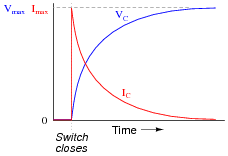
Graph both the capacitor voltage (VC) and the capacitor current (IC) over time as the switch is closed in this circuit. Assume the capacitor begins in a complete uncharged state (0 volts):
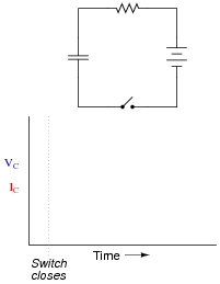
|
|
Then, select and modify the appropriate form of equation (from below) to describe each plot:
|
|
|
|
|
Notes:
Have your students explain why the voltage and current curves are shaped as they are.
Question 7:
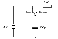
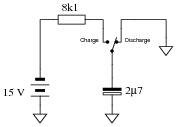
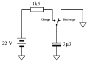
The following circuit allows a capacitor to be rapidly charged and slowly discharged:
|
|
Suppose that the switch was left in the "charge" position for some substantial amount of time. Then, someone moves the switch to the "discharge" position to let the capacitor discharge. Calculate the amount of capacitor voltage and capacitor current at exactly 3 seconds after moving the switch to the "discharge" position.
VC = @ t = 3 seconds
IC = @ t = 3 seconds
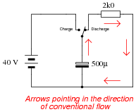
Also, show the direction of discharge current in this circuit.
IC = 995.74 mA @ t = 3 seconds
|
|
Notes:
Here, students must choose which equation(s) to use for the calculation, calculate the time constant for the circuit, and put all the variables in the right place to obtain the correct answers. Discuss all these steps with your students, allowing them to explain how they approached the question.
If anyone asks, let them know that the capacitor symbol shown represents a polarized (electrolytic) capacitor.
Question 8:
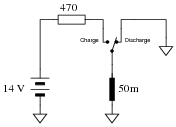
The following circuit allows a capacitor to be rapidly discharged and slowly charged:
|
|
Suppose that the switch was left in the "discharge" position for some substantial amount of time. Then, someone moves the switch to the "charge" position to let the capacitor charge. Calculate the amount of capacitor voltage and capacitor current at exactly 45 milliseconds after moving the switch to the "charge" position.
VC = @ t = 45 ms
IC = @ t = 45 ms
IC = 236.6 mA @ t = 45 ms
Follow-up question: show the directions of charge and discharge current in this circuit.
Notes:
Here, students must choose which equation(s) to use for the calculation, calculate the time constant for the circuit, and put all the variables in the right place to obtain the correct answers. Discuss all these steps with your students, allowing them to explain how they approached the question.
If anyone asks, let them know that the capacitor symbol shown represents a polarized (electrolytic) capacitor.
Question 9:
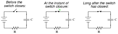
Qualitatively determine the voltages across all components as well as the current through all components in this simple RC circuit at three different times: (1) just before the switch closes, (2) at the instant the switch contacts touch, and (3) after the switch has been closed for a long time. Assume that the capacitor begins in a completely discharged state:
|
|
Express your answers qualitatively: "maximum," "minimum," or perhaps "zero" if you know that to be the case.
Before the switch closes:
VC =
VR =
Vswitch =
I =
At the instant of switch closure:
VC =
VR =
Vswitch =
I =
Long after the switch has closed:
VC =
VR =
Vswitch =
I =
Hint: a graph may be a helpful tool for determining the answers!
VC = zero
VR = zero
Vswitch = maximum
I = zero
At the instant of switch closure:
VC = zero
VR = maximum
Vswitch = zero
I = maximum
Long after the switch has closed:
VC = maximum
VR = zero
Vswitch = zero
I = zero
Follow-up question: which of these variables remained the same immediately before and immediately after switch closure? Explain why.
Notes:
The purpose of this question is to preview the concept of ïnitial" and "final" values in RC circuits, before they learn to use the üniversal time constant formula."
Question 10:
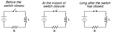
Qualitatively determine the voltages across all components as well as the current through all components in this simple LR circuit at three different times: (1) just before the switch closes, (2) at the instant the switch contacts touch, and (3) after the switch has been closed for a long time.
|
|
Express your answers qualitatively: "maximum," "minimum," or perhaps "zero" if you know that to be the case.
Before the switch closes:
VL =
VR =
Vswitch =
I =
At the instant of switch closure:
VL =
VR =
Vswitch =
I =
Long after the switch has closed:
VL =
VR =
Vswitch =
I =
Hint: a graph may be a helpful tool for determining the answers!
VL = zero
VR = zero
Vswitch = maximum
I = zero
At the instant of switch closure:
VL = maximum
VR = zero
Vswitch = zero
I = zero
Long after the switch has closed:
VL = zero
VR = maximum
Vswitch = zero
I = maximum
Follow-up question: which of these variables remained the same immediately before and immediately after switch closure? Explain why.
Notes:
The purpose of this question is to preview the concept of ïnitial" and "final" values in RC circuits, before they learn to use the üniversal time constant formula."
Question 11:
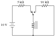
Calculate the final value of current through the inductor with the switch in the left-hand position (assuming that many time constants' worth of time have passed):
|
|
Now, assume that the switch is instantly moved to the right-hand position. How much voltage will the inductor initially drop?
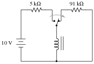
|
|
Explain why this voltage is so very different from the supply voltage. What practical uses might a circuit such as this have?
Vswitch-right = 182 V
Follow-up question: suppose this circuit were built and tested, and it was found that the voltage developed across the inductor at the moment the switch moved to the right-hand position far exceeded 182 volts. Identify some possible problems in the circuit which could account for this excessive voltage.
Notes:
The main purpose of this question is to get students thinking in terms of ïnitial" and "final" values for LR circuits, and how one might calculate them. It is largely a conceptual question, with just a bit of calculation necessary.
One practical application of this circuit is for ßtepping up" DC voltage. The circuit topology shown in the question is that of an inverting converter circuit. This form of DC-DC converter circuit has the ability to step voltage up or down, depending on the duty cycle of the switch's oscillation.
Question 12:
An unfortunate tendency that many new students have is to immediately plug numbers into equations when faced with a time-constant circuit problem, before carefully considering the circuit. Explain why the following steps are very wise to follow before performing any mathematical calculations:
- �
- Step 1: Identify and list all the known ("given") quantities.
- �
- Step 2: Draw a schematic of the circuit, if none is given to you.
- �
- Step 3: Label components in the schematic with all known quantities.
- �
- Step 4: Sketch a rough plot of how you expect the variable(s) in the circuit to change over time.
- �
- Step 5: Label starting and final values for these graphed variables, wherever possible.
Notes:
This is advice I always give my students, after seeing so many students get themselves into trouble by blindly plugging numbers into equations. Think before you act, is the motto here!
Actually, this general advice applies to most all physics-type problems: identify what it is you're trying to solve and what you have to work with before jumping into calculations.
Question 13:
Suppose a capacitor is charged to a voltage of exactly 100 volts, then connected to a resistor so it discharges slowly. Calculate the amount of voltage remaining across the capacitor terminals at the following points in time:
- �
- 1 time constant (t) after connecting the resistor:
- �
- 2 time constants (2t) after connecting the resistor:
- �
- 3 time constants (3t) after connecting the resistor:
- �
- 4 time constants (4t) after connecting the resistor:
- �
- 5 time constants (5t) after connecting the resistor:
- �
- 1 time constant (t) after connecting the resistor: VC = 36.79 volts
- �
- 2 time constants (2t) after connecting the resistor: VC = 13.53 volts
- �
- 3 time constants (3t) after connecting the resistor: VC = 4.979 volts
- �
- 4 time constants (4t) after connecting the resistor: VC = 1.832 volts
- �
- 5 time constants (5t) after connecting the resistor: VC = 0.6738 volts
Follow-up question: write an equation solving for these voltages at the specified times.
Notes:
Although students should be able to look up approximate answers to this question from almost any beginning electronics textbook, the point here is to get them to relate the question to an actual formula so they may calculate this on their own.
Question 14:
Calculate the voltage across a 470 mF capacitor after discharging through a 10 kW resistor for 9 seconds, if the capacitor's original voltage (at t = 0) was 24 volts.
Also, express this amount of time (9 seconds) in terms of how many time constants have elapsed.
9 s = 1.915 time constants (1.915t)
Notes:
Here, students must choose which equation to use for the calculation, calculate the time constant for the circuit, and put all the variables in the right place to obtain the correct answer. Discuss all these steps with your students, allowing them to explain how they approached the question.
Question 15:
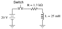
Calculate the current through a 250 mH inductor after "charging" through a series-connected resistor with 100 W of resistance for 6 milliseconds, powered by a 12 volt battery. Assume that the inductor is perfect, with no internal resistance.
Also, express this amount of time (6 milliseconds) in terms of how many time constants have elapsed.
6 ms = 2.4 time constants (2.4t)
Notes:
Here, students must choose which equation to use for the calculation, calculate the time constant for the circuit, and put all the variables in the right place to obtain the correct answer. Discuss all these steps with your students, allowing them to explain how they approached the question.
Question 16:
Determine the capacitor voltage at the specified times (time t = 0 milliseconds being the exact moment the switch contacts close). Assume the capacitor begins in a fully discharged state:
|
|
-
Time VC (volts)
0 ms
30 ms
60 ms
90 ms
120 ms
150 ms
-
Time VC (volts)
0 ms 0
30 ms 12.29
60 ms 19.71
90 ms 24.19
120 ms 26.89
150 ms 28.52
Notes:
Be sure to have your students share their problem-solving techniques (how they determined which equation to use, etc.) in class.
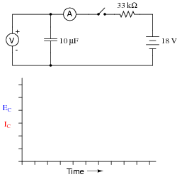
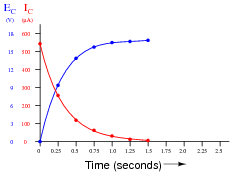
Question 17:
Plot the capacitor voltage and the capacitor current over time after the switch closes in this circuit, for at least 4 time constants' worth of time:
|
|
Be sure to label the axes of your graph!
|
|
Notes:
I intentionally left the graph unscaled in the problem, so that students might determine their own scales to plot the points in. The scaling shown in the answer is obviously not ideal, as the graphs have reached their terminal values (for all practical purposes) well before the horizontal axis is complete.
Question 18:
Plot the inductor voltage and the inductor current over time after the switch closes in this circuit, for at least 4 time constants' worth of time:
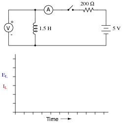
|
|
Be sure to label the axes of your graph!
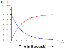
|
|
Notes:
I intentionally left the graph unscaled in the problem, so that students might determine their own scales to plot the points in. The scaling shown in the answer is obviously not ideal, as the graphs have reached their terminal values (for all practical purposes) well before the horizontal axis is complete.
Question 19:
Calculate the amount of time it takes for a 33 mF capacitor to charge from 0 volts to 20 volts, if powered by a 24 volt battery through a 10 kW resistor.
Notes:
In order for students to solve this problem, they must algebraically manipulate the "normal" time-constant formula to solve for time instead of solving for voltage.
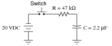
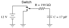
Question 20:
Determine the amount of time needed after switch closure for the capacitor voltage (VC) to reach the specified levels:
|
|
-
VC Time
0 volts
10 volts
20 volts
30 volts
40 volts
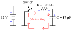
Trace the direction of electron flow in the circuit, and also mark all voltage polarities.
|
|
-
VC Time
0 volts 0 ms
10 volts 297.5 ms
20 volts 716.7 ms
30 volts 1.433 s
40 volts > 5 s
Notes:
Some students may write 5.17 seconds as the time required to charge to 40 volts (5 time constants' worth of time). If so, remind them that the ßtandard" of 5t is arbitrary, and that theoretically the capacitor never actually reaches full charge.
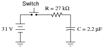
Question 21:
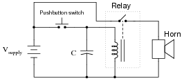
A simple time-delay relay circuit may be built using a large capacitor connected in parallel with the relay coil, to temporarily supply the relay coil with power after the main power source is disconnected. In the following circuit, pressing the pushbutton switch sounds the horn, which remains on for a brief time after releasing the switch:
|
|
To calculate the amount of time the horn will remain on after the pushbutton switch is released, we must know a few things about the relay itself. Since the relay coil acts as a resistive load to the capacitor, we must know the coil's resistance in ohms. We must also know the voltage at which the relay "drops out" (i.e. the point at which there is too little voltage across the coil to maintain a strong enough magnetic field to hold the relay contacts closed).
Suppose the power supply voltage is 24 volts, the capacitor is 2200 mF, the relay coil resistance is 500 W, and the coil drop-out voltage is 6.5 volts. Calculate how long the time delay will last.
Notes:
In order for students to solve this problem, they must algebraically manipulate the "normal" time-constant formula to solve for time instead of solving for voltage.
Question 22:
Design an experiment to calculate the size of a capacitor based on its response in a time-constant circuit. Include in your design an equation that gives the value of the capacitor in farads, based on data obtained by running the experiment.
|
|
The equation is yours to develop - I will not reveal it here. However, this does not mean there is no way to verify the accuracy of your equation, once you write it. Explain how it would be possible to prove the accuracy of your algebra, once you have written the equation.
Notes:
In developing equations, students often feel äbandoned" if the instructor does not provide an answer for them. How will they ever know if their equation is correct? If the phenomenon the equation seeks to predict is well-understood, though, this is not a problem.
Question 23:
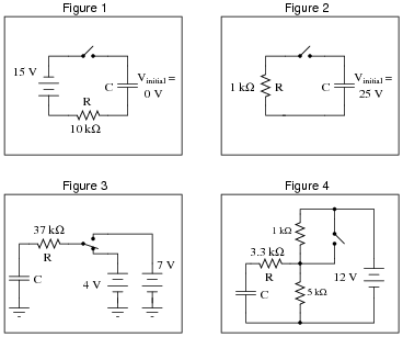
A helpful technique for analyzing RC time-constant circuits is to consider what the initial and final values for circuit variables (voltage and current) are. Consider these four RC circuits:
|
|
In each of these circuits, determine what the initial values will be for voltage across and current through both the capacitor and (labeled) resistor. These will be the voltage and current values at the very first instant the switch changes state from where it is shown in the schematic. Also, determine what the final values will be for the same variables (after a large enough time has passed that the variables are all ßettled" into their ultimate values). The capacitor's initial voltage is shown in all cases where it is arbitrary.
| VC(initial) = 0 V (given) | VC(final) = 15 V |
| IC(initial) = 1.5 mA | IC(final) = 0 mA |
| VR(initial) = 15 V | VR(final) = 0 V |
| IR(initial) = 1.5 mA | IR(final) = 0 mA |
Figure 2:
| VC(initial) = 25 V (given) | VC(final) = 0 V |
| IC(initial) = 25 mA | IC(final) = 0 mA |
| VR(initial) = 25 V | VR(final) = 0 V |
| IR(initial) = 25 mA | IR(final) = 0 mA |
Figure 3:
| VC(initial) = 4 V | VC(final) = 7 V |
| IC(initial) = 81 mA | IC(final) = 0 mA |
| VR(initial) = 3 V | VR(final) = 0 V |
| IR(initial) = 81 mA | IR(final) = 0 mA |
Figure 4:
| VC(initial) = 10 V | VC(final) = 12 V |
| IC(initial) = 606 mA | IC(final) = 0 mA |
| VR(initial) = 2 V | VR(final) = 0 V |
| IR(initial) = 606 mA | IR(final) = 0 mA |
Follow-up question: explain why the inductor value (in Henrys) is irrelevant in determining ïnitial" and "final" values of voltage and current.
Notes:
Once students grasp the concept of initial and final values in time-constant circuits, they may calculate any variable at any point in time for any RC or LR circuit (not for RLC circuits, though, as these require the solution of a second-order differential equation!). All they need is the universal time-constant equation:
|
(x, of course, represents either voltage or current, depending on what is being calculated.)
One common mistake new students often commit is to consider ïnitial" values as those values of voltage and current existing in the circuit before the switch is thrown. However, ïnitial" refers to those values at the very first instant the switch moves to its new position, not before.
Question 24:
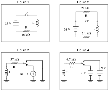
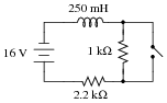
A helpful technique for analyzing LR time-constant circuits is to consider what the initial and final values for circuit variables (voltage and current) are. Consider these four LR circuits:
|
|
In each of these circuits, determine what the initial values will be for voltage across and current through both the inductor and (labeled) resistor. These will be the voltage and current values at the very first instant the switch changes state from where it is shown in the schematic. Also, determine what the final values will be for the same variables (after a large enough time has passed that the variables are all ßettled" into their ultimate values).
Assume all inductors are ideal, possessing no coil resistance (Rcoil = 0 W).
| VL(initial) = 15 V | VL(final) = 0 V |
| IL(initial) = 0 mA | IL(final) = 1.5 mA |
| VR(initial) = 0 V | VR(final) = 15 V |
| IR(initial) = 0 mA | IR(final) = 1.5 mA |
Figure 2:
| VL(initial) = 50.4 V | VL(final) = 0 V |
| IL(initial) = 3.38 mA | IL(final) = 825 mA |
| VR(initial) = 74.4 V | VR(final) = 18.1 V |
| IR(initial) = 3.38 mA | IR(final) = 825 mA |
Figure 3:
| VL(initial) = 370 V | VL(final) = 0 V |
| IL(initial) = 10 mA | IL(final) = 0 mA |
| VR(initial) = 370 V | VR(final) = 0 V |
| IR(initial) = 10 mA | IR(final) = 0 mA |
Figure 4:
| VL(initial) = 6 V | VL(final) = 0 V |
| IL(initial) = 638 mA | IL(final) = 1.91 mA |
| VR(initial) = 3 V | VR(final) = 9 V |
| IR(initial) = 638 mA | IR(final) = 1.91 mA |
Follow-up question: explain why the inductor value (in Henrys) is irrelevant in determining ïnitial" and "final" values of voltage and current.
Notes:
Once students grasp the concept of initial and final values in time-constant circuits, they may calculate any variable at any point in time for any RC or LR circuit (not for RLC circuits, though, as these require the solution of a second-order differential equation!). All they need is the universal time-constant equation:
|
(x, of course, represents either voltage or current, depending on what is being calculated.)
One common mistake new students often commit is to consider ïnitial" values as those values of voltage and current existing in the circuit before the switch is thrown. However, ïnitial" refers to those values at the very first instant the switch moves to its new position, not before.
Question 25:
A formula I like to use in calculating voltage and current values in either RC or LR circuits has two forms, one for voltage and one for current:
|
|
The "0" subscript represents the condition at time = 0 (V0 or I0, respectively), representing the ïnitial" value of that variable. The "f" subscript represents the "final" or ültimate" value that the voltage or current would achieve if allowed to progress indefinitely. Obviously, one must know how to determine the ïnitial" and "final" values in order to use either of these formulae, but once you do you will be able to calculate any voltage and any current at any time in either an RC or LR circuit.
What is not so obvious to students is how each formula works. Specifically, what does each portion of it represent, in practical terms? This is your task: to describe what each term of the equation means in your own words. I will list the "voltage" formula terms individually for you to define:
|
|
|
( Vf - V0 ) represents the amount of change that the voltage would go through, from the start of the charge/discharge cycle until eternity. Note that the sign (positive or negative) of this term is very important!
( 1 - [1/(e[t/(t)])] ) is the fractional value (between 0 and 1, inclusive) expressing how far the voltage has changed from its initial value to its final value.
Follow-up question: why is it important to add the final V0 term to the expression? Why not leave the formula at V(t) = ( Vf - V0 ) ( 1 - [1/(e[t/(t)])] ) ?
Notes:
This so-called üniversal time-constant formula" is my own (Tony R. Kuphaldt's) invention. A product of frustration from trying to teach students to calculate variables in RC and LR time-constant circuits using one formula for decay and another one for increasing values, this equation works for all conditions. Vitally important to this formula's accuracy, however, is that the student correctly assesses the initial and final values. This is the biggest problem I see students having when they go to calculate voltages or currents in time-constant circuits.
In my Lessons In Electric Circuits textbook, I introduce this formula in a slightly different form:
|
This explains the purpose of my follow-up question: to challenge students who might simply read the book's version of the formula and not consider the difference between it and what is presented here!
Question 26:
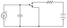
Determine the voltage across the capacitor three seconds after the switch is moved from the upper position to the lower position, assuming it had been left in the upper position for a long time:
|
|
Follow-up question: identify at least one failure in this circuit which would cause the capacitor to remain completely discharged no matter what position the switch was in.
Notes:
This problem is unique in that the capacitor does not discharge all the way to 0 volts when the switch is moved to the lower position. Instead, it discharges down to a (final) value of 3 volts. Solving for the answer requires that students be a bit creative with the common time-constant equations (e-[t/(t)] and 1 - e-[t/(t)]).
The follow-up question is simply an exercise in troubleshooting theory.
Question 27:
Calculate the voltage across the switch contacts the exact moment they open, and 15 milliseconds after they have been opened:
|
|
Eswitch = 9.531 V @ t = 15 milliseconds
Follow-up question: predict all voltage drops in this circuit in the event that the inductor fails open (broken wire inside).
Notes:
There is quite a lot to calculate in order to reach the solutions in this question. There is more than one valid way to approach it, as well. An important fact to note: the voltage across the switch contacts, in both examples, is greater than the battery voltage! Just as capacitive time-constant circuits can generate currents in excess of what their power sources can supply, inductive time-constant circuits can generate voltages in excess of what their power sources can supply.
The follow-up question is simply an exercise in troubleshooting theory.
Question 28:
The decay of a variable (either voltage or current) in a time-constant circuit (RC or LR) follows this mathematical expression:
|
Where,
e = Euler's constant ( � 2.718281828)
t = Time, in seconds
t = Time constant of circuit, in seconds
Calculate the value of this expression as t increases, given a circuit time constant (t) of 1 second. Express this value as a percentage:
- t = 1 second
- t = 2 seconds
- t = 3 seconds
- t = 4 seconds
- t = 5 seconds
- t = 6 seconds
- t = 7 seconds
- t = 8 seconds
- t = 9 seconds
- t = 10 seconds
Based on your calculations, how would you describe the change in the expression's value over time as t increases?
- t = 1 second ; e-[t/(t)] = 36.788%
- t = 2 seconds ; e-[t/(t)] = 13.534%
- t = 3 seconds ; e-[t/(t)] = 4.979%
- t = 4 seconds ; e-[t/(t)] = 1.832%
- t = 5 seconds ; e-[t/(t)] = 0.6738%
- t = 6 seconds ; e-[t/(t)] = 0.2479%
- t = 7 seconds ; e-[t/(t)] = 0.09119%
- t = 8 seconds ; e-[t/(t)] = 0.03355%
- t = 9 seconds ; e-[t/(t)] = 0.01234%
- t = 10 seconds ; e-[t/(t)] = 0.004540%
Notes:
The purpose of this question is for students to learn the significance of the expression e-[t/(t)] by "playing" with the numbers. The negative exponent may confuse some students, so be sure to discuss its significance with all students, so that all understand what it means.
Another concept for students to grasp in this question is that of an asymptotic function: a function that approaches a final value in incrementally smaller intervals.
Question 29:
The decay of a variable (either voltage or current) in a time-constant circuit (RC or LR) follows this mathematical expression:
|
Where,
e = Euler's constant ( � 2.718281828)
t = Time, in seconds
t = Time constant of circuit, in seconds
Calculate the value of this expression as t increases, given a circuit time constant (t) of 2 seconds. Express this value as a percentage:
- t = 1 second
- t = 2 seconds
- t = 3 seconds
- t = 4 seconds
- t = 5 seconds
- t = 6 seconds
- t = 7 seconds
- t = 8 seconds
- t = 9 seconds
- t = 10 seconds
Also, express the percentage value of any increasing variables (either voltage or current) in an RC or LR charging circuit, for the same conditions (same times, same time constant).
- t = 1 second ; e-[t/(t)] = 60.65% ; increasing variable = 39.35%
- t = 2 seconds ; e-[t/(t)] = 36.79% ; increasing variable = 63.21%
- t = 3 seconds ; e-[t/(t)] = 22.31% ; increasing variable = 77.69%
- t = 4 seconds ; e-[t/(t)] = 13.53% ; increasing variable = 86.47%
- t = 5 seconds ; e-[t/(t)] = 8.208% ; increasing variable = 91.79%
- t = 6 seconds ; e-[t/(t)] = 4.979% ; increasing variable = 95.02%
- t = 7 seconds ; e-[t/(t)] = 3.020% ; increasing variable = 96.98%
- t = 8 seconds ; e-[t/(t)] = 1.832% ; increasing variable = 98.17%
- t = 9 seconds ; e-[t/(t)] = 1.111% ; increasing variable = 98.89%
- t = 10 seconds ; e-[t/(t)] = 0.6738% ; increasing variable = 99.33%
Notes:
Do not simply tell your students how to calculate the values of the increasing variable. Based on their qualitative knowledge of time-constant circuit curves and their ability to evaluate the downward (decay) expression, they should be able to figure out how to calculate the increasing variable's value over time as well.
Some students will insist that you give them an equation to do this. They want to be told what to do, rather than solve the problem on their own based on an observation of pattern. It is very important that students of any science learn to recognize patterns in data, and that they learn to fit that data into a mathematical equation. If nothing else, these figures given in the answer for both decreasing and increasing variables should be plain enough.
Question 30:
Write a mathematical expression for calculating the percentage value of any increasing variables (either voltage or current) in an RC or LR time-constant circuit.
Hint: the formula for calculating the percentage of any decreasing variables in an RC or LC time-constant circuit is as follows:
|
Where,
e = Euler's constant ( � 2.718281828)
t = Time, in seconds
t = Time constant of circuit, in seconds
Here, the value of the expression starts at 1 (100%) at time = 0 and approaches 0 (0%) as time approaches �. What I'm asking you to derive is an equation that does just the opposite: start with a value of 0 when time = 0 and approach a value of 1 as time approaches �.
|
Notes:
Being able to derive an equation from numerical data is a complex, but highly useful, skill in all the sciences. Sure, your students will be able to find this mathematical expression in virtually any basic electronics textbook, but the point of this question is to derive this expression from an examination of data (and, of course, an examination of the other time-constant expression: e-[t/(t)]).
Be sure to challenge your students to do this, by asking how they obtained the answer to this question. Do not ßettle" for students simply telling you what the equation is - ask them to explain their problem-solving techniques, being sure that all students have contributed their insights.
Question 31:
Calculating variables in reactive circuits using time-constant formulae can be time consuming, due to all the keystrokes necessary on a calculator. Even worse is when a calculator is not available! You should be prepared to estimate circuit values without the benefit of a calculator to do the math, though, because a calculator may not always be available when you need one.
Note that Euler's constant (e) is approximately equal to 3. This is not a close approximation, but close enough for "rough" estimations. If we use a value of three instead of e's true value of 2.718281828�, we may greatly simplify the "decay" time constant formula:
|
Suppose that a capacitive discharge circuit begins with a full-charge voltage of 10 volts. Calculate the capacitor's voltage at the following times as it discharges, assuming t = 1 second:
- t = 0 seconds ; EC =
- t = 1 second ; EC =
- t = 2 seconds ; EC =
- t = 3 seconds ; EC =
- t = 4 seconds ; EC =
- t = 5 seconds ; EC =
Without using a calculator, you should at least be able to calculate voltage values as fractions if not decimals!
- t = 0 seconds ; EC = 10 V
- t = 1 second ; EC = [10/3] V = 3.33 V
- t = 2 seconds ; EC = [10/9] V = 1.11 V
- t = 3 seconds ; EC = [10/27] V = 0.370 V
- t = 4 seconds ; EC = [10/81] V = 0.123 V
- t = 5 seconds ; EC = [10/243] V = 0.0412 V
Notes:
Calculating the voltage for the first few time constants' worth of time should be easy without a calculator. I strongly encourage your students to develop their estimation skills, so that they may solve problems without being dependent upon a calculator. Too many students depend heavily on calculators - some are even dependent on specific brands or models of calculators!
Equally important as being able to estimate is knowing whether or not your estimations are over or under the exact values. This is especially true when estimating quantities relevant to safety and/or reliability!
Question 32:
Calculating variables in reactive circuits using time-constant formulae can be time consuming, due to all the keystrokes necessary on a calculator. Even worse is when a calculator is not available! You should be prepared to estimate circuit values without the benefit of a calculator to do the math, though, because a calculator may not always be available when you need one.
Note that Euler's constant (e) is approximately equal to 3. This is not a close approximation, but close enough for "rough" estimations. If we use a value of three instead of e's true value of 2.718281828�, we may greatly simplify the ïncreasing" time constant formula:
|
Suppose that a capacitive charging circuit begins fully discharged (0 volts), and charges to an ultimate value of 10 volts. Calculate the capacitor's voltage at the following times as it discharges, assuming t = 1 second:
- t = 0 seconds ; EC =
- t = 1 second ; EC =
- t = 2 seconds ; EC =
- t = 3 seconds ; EC =
- t = 4 seconds ; EC =
- t = 5 seconds ; EC =
Without using a calculator, you should at least be able to calculate voltage values as fractions if not decimals!
- t = 0 seconds ; EC = 0 V
- t = 1 second ; EC = [20/3] V = 6.67 V
- t = 2 seconds ; EC = [80/9] V = 8.89 V
- t = 3 seconds ; EC = [260/27] V = 9.63 V
- t = 4 seconds ; EC = [800/81] V = 9.88 V
- t = 5 seconds ; EC = [2420/243] V = 9.96 V
Notes:
Calculating the voltage for the first few time constants' worth of time should be easy without a calculator. I strongly encourage your students to develop their estimation skills, so that they may solve problems without being dependent upon a calculator. Too many students depend heavily on calculators - some are even dependent on specific brands or models of calculators!
Equally important as being able to estimate is knowing whether or not your estimations are over or under the exact values. This is especially true when estimating quantities relevant to safety and/or reliability!
Question 33:
Determine the number of time constants (t) that 7.5 seconds is equal to in each of the following reactive circuits:
- �
- RC circuit; R = 10 kW, C = 220 mF ; 7.5 sec =
- �
- RC circuit; R = 33 kW, C = 470 mF ; 7.5 sec =
- �
- RC circuit; R = 1.5 kW, C = 100 mF ; 7.5 sec =
- �
- RC circuit; R = 790 W, C = 9240 nF ; 7.5 sec =
- �
- RC circuit; R = 100 kW, C = 33 pF ; 7.5 sec =
- �
- LR circuit; R = 100 W, L = 50 mH ; 7.5 sec =
- �
- LR circuit; R = 45 W, L = 2.2 H ; 7.5 sec =
- �
- LR circuit; R = 1 kW, L = 725 mH ; 7.5 sec =
- �
- LR circuit; R = 4.7 kW, L = 325 mH ; 7.5 sec =
- �
- LR circuit; R = 6.2 W, L = 25 H ; 7.5 sec =
- �
- RC circuit; R = 10 kW, C = 220 mF ; 7.5 sec = 3.41 t
- �
- RC circuit; R = 33 kW, C = 470 mF ; 7.5 sec = 0.484 t
- �
- RC circuit; R = 1.5 kW, C = 100 mF ; 7.5 sec = 50.0 t
- �
- RC circuit; R = 790 W, C = 9240 nF ; 7.5 sec = 1027 t
- �
- RC circuit; R = 100 kW, C = 33 pF ; 7.5 sec = 2,272,727 t
- �
- LR circuit; R = 100 W, L = 50 mH ; 7.5 sec = 15,000 t
- �
- LR circuit; R = 45 W, L = 2.2 H ; 7.5 sec = 153.4 t
- �
- LR circuit; R = 1 kW, L = 725 mH ; 7.5 sec = 10,345 t
- �
- LR circuit; R = 4.7 kW, L = 325 mH ; 7.5 sec = 108,462 t
- �
- LR circuit; R = 6.2 W, L = 25 H ; 7.5 sec = 1.86 t
Notes:
An interesting thing to note here is the span of time constant values available from common capacitor/inductor/resistor sizes. As students should notice, the capacitor-resistor combinations (all very practical values, I might add) create both longer and shorter time constant values than the inductor-resistor combinations, and that is even including the 25 Henry - 6.2 Ohm combination, which would be difficult (read: expensive) to achieve in real life.
Question 34:
At a party, you happen to notice a mathematician taking notes while looking over the food table where several pizzas are set. Walking up to her, you ask what she is doing. Ï'm mathematically modeling the consumption of pizza," she tells you. Before you have the chance to ask another question, she sets her notepad down on the table and excuses herself to go use the bathroom.
Looking at the notepad, you see the following equation:
|
Where,
t = Time in minutes since arrival of pizza.
The problem is, you don't know whether the equation she wrote describes the percentage of pizza eaten or the percentage of pizza remaining on the table. Explain how you would determine which percentage this equation describes. How, exactly, can you tell if this equation describes the amount of pizza already eaten or the amount of pizza that remains to be eaten?
Notes:
While some may wonder what this question has to do with electronics, it is an exercise in qualitative analysis. This skill is very important for students to master if they are to be able to distinguish between the equations e-[t/(t)] and 1 - e-[t/(t)], both used in time-constant circuit analysis.
The actual procedure for determining the nature of the equation is simple: consider what happens as t begins at 0 and as it increases to some arbitrary positive value. Some students may rely on their calculators, performing actual calculations to see whether the percentage increases or decreases with increasing t. Encourage them to analyze the equation qualitatively rather than quantitatively, though. They should be able to tell which way the percentage changes with time without having to consider a single numerical value!
Question 35:
The following expression is frequently used to calculate values of changing variables (voltage and current) in RC and LR timing circuits:
|
If we evaluate this expression for a time of t = 0, we find that it is equal to 1 (100%). If we evaluate this expression for increasingly larger values of time (t � �), we find that it approaches 0 (0%).
Based on this simple analysis, would you say that the expression e-[t/(t)] describes the percentage that a variable has changed from its initial value in a timing circuit, or the percentage that it has left to change before it reaches its final value? To frame this question in graphical terms . . .
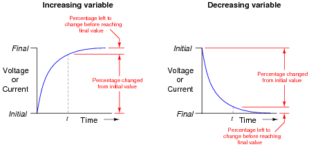
|
|
Which percentage does the expression e-[t/(t)] represent in each case? Explain your answer.
Follow-up question: what could you add to or modify about the expression to make it describe the percentage that a variable has already changed from its initial value? In other words, alter the expression so that it is equal to 0% at t = 0 and approaches 100% as t grows larger (t � �).
Notes:
It is very important for students to understand what this expression means and how it works, lest they rely solely on memorization to use it in their calculations. As I always tell my students, rote memorization will fail you! If a student does not comprehend why the expression works as it does, they will be helpless to retain it as an effective "tool" for performing calculations in the future.
A good way to suggest students approach a problem such as this is to imagine t increasing in value. As t grows larger, what happens to the expression's overall value? Then, compare which of the two percentages (percentage traversed, or percentage remaining) follow the same trend. One not need touch a calculator to figure this out!
Question 36:
Determine the capacitor voltage and capacitor current at the specified times (time t = 0 milliseconds being the exact moment the switch contacts close). Assume the capacitor begins in a fully discharged state:
|
|
-
Time VC (volts) IC (mA)
0 ms
30 ms
60 ms
90 ms
120 ms
150 ms
-
Time VC (volts) IC (mA)
0 ms 0 4.255
30 ms 6.932 2.781
60 ms 11.46 1.817
90 ms 14.42 1.187
120 ms 16.35 0.7757
150 ms 17.62 0.5069
Notes:
Be sure to have your students share their problem-solving techniques (how they determined which equation to use, etc.) in class.
Question 37:
Determine the inductor voltage and inductor current at the specified times (time t = 0 milliseconds being the exact moment the switch contacts close):
|
|
-
Time VL (volts) IL (mA)
0 ms
10 ms
20 ms
30 ms
40 ms
50 ms
-
Time VL (volts) IL (mA)
0 ms 20 0
10 ms 11.89 6.238
20 ms 7.069 9.947
30 ms 4.203 12.15
40 ms 2.499 13.46
50 ms 1.485 14.24
Notes:
Be sure to have your students share their problem-solving techniques (how they determined which equation to use, etc.) in class.
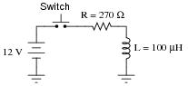
Question 38:
Determine the inductor voltage and inductor current at the specified times (time t = 0 milliseconds being the exact moment the switch contacts close):
|
|
-
Time VL (volts) IL (mA)
0 ns
250 ns
500 ns
750 ns
1.00 ms
1.25 ms
-
Time VL (volts) IL (mA)
0 ns 12 0
250 ns 6.110 21.82
500 ns 3.111 32.92
750 ns 1.584 38.58
1.00 ms 0.8065 41.46
1.25 ms 0.4106 42.93
Notes:
Be sure to have your students share their problem-solving techniques (how they determined which equation to use, etc.) in class.
Question 39:
Complete this table of values for inductor voltage and current. Consider time = 0 to be the precise moment the switch closes:
|
|
-
Time (ms) VL (V) IL (mA)
0
50
100
150
200
250
300
350
400
-
Time (ms) VL (V) IL (mA)
0 5.00 5.00
50 3.22 5.81
100 2.07 6.33
150 1.34 6.67
200 0.860 6.88
250 0.554 7.02
300 0.357 7.11
350 0.230 7.17
400 0.148 7.21
Notes:
This circuit demands careful pre-analysis of the initial and final values. If students experience difficulty calculating the voltage and current figures here, it is probably due to incorrect initial and final values for voltage and/or current.
Question 40:
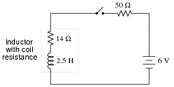
Calculate the voltage across a 2.5 H inductor after "charging" through a series-connected resistor with 50 W of resistance for 75 milliseconds, powered by a 6 volt battery. Assume that the inductor has an internal resistance of 14 W.
Also, express this amount of time (75 milliseconds) in terms of how many time constants have elapsed.
Hint: it would be helpful in your analysis to draw a schematic diagram of this circuit showing the inductor's inductance and 14 ohms of resistance as two separate (idealized) components. This is a very common analysis technique in electrical engineering: to regard the parasitic characteristics of a component as a separate component in the same circuit.
|
|
EL = 2.00 V @ t = 75 milliseconds
75 ms = 1.92 time constants (1.92t)
Notes:
Although I have revealed a problem-solving technique in this question, it does not show the students exactly how to separate the inductor's 2.5 henrys of inductance and 14 ohms of resistance into two components, nor does it give away the answer. Discuss the analytical technique of drawing idealized components ("lumped parameters") as a problem-solving technique, and encourage students to use it whenever they are faced with analyzing a component exhibiting parasitic characteristics.
An excellent example of this technique is in "modeling" transformers. Transformers exhibit much more than just mutual inductance. They also exhibit self-inductance, leakage inductance, capacitance, resistance, and hysteretic losses. A comprehensive model for a transformer is a very complex thing, and it appears on a schematic to be a whole network of components connected together:
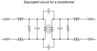
|
|
Each of these components is regarded as ideal (i.e., pure: possessing no parasitic characteristics), but together they "model" the behavior of a real transformer in terms readily applicable to existing mathematical techniques.
Question 41:
Calculate the amount of time it takes for a 10 mF capacitor to discharge from 18 volts to 7 volts if its ultimate (final) voltage when fully discharged will be 0 volts, and it is discharging through a 22 kW resistor.
Notes:
In order for students to solve this problem, they must algebraically manipulate the "normal" time-constant formula to solve for time instead of solving for voltage.
Question 42:
Determine the amount of time needed after switch closure for the capacitor voltage (VC) to reach the specified levels:
|
|
-
VC Time
0 volts
-5 volts
-10 volts
-15 volts
-19 volts
Trace the direction of current in the circuit while the capacitor is charging, and be sure to denote whether you are using electron or conventional flow notation.
Note: the voltages are specified as negative quantities because they are negative with respect to (positive) ground in this particular circuit.
-
VC Time
0 volts 0 ms
-5 volts 29.75 ms
-10 volts 71.67 ms
-15 volts 143.3 ms
-19 volts 309.8 ms
While the capacitor is charging, electron flow moves clockwise and conventional flow moves counter-clockwise.
Notes:
Ask your students to show how they algebraically solved the standard time constant equation for t using logarithms.
Question 43:
Determine the amount of time needed for the capacitor voltage (VC) to fall to the specified levels after the switch is thrown to the "discharge" position, assuming it had first been charged to full battery voltage:
|
|
-
VC Time
10 volts
8 volts
6 volts
4 volts
2 volts
Trace the direction of electron flow in the circuit, and also mark all voltage polarities.
|
|
-
VC Time
10 volts 588.9 ms
8 volts 1.31 s
6 volts 2.24 s
4 volts 3.55 s
2 volts 5.79 s
Notes:
Ask your students to explain how they set up each calculation.
Question 44:
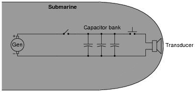
A submarine sonar system uses a "bank" of parallel-connected capacitors to store the electrical energy needed to send brief, powerful pulses of current to a transducer (a ßpeaker" of sorts). This generates powerful sound waves in the water, which are then used for echo-location. The capacitor bank relieves the electrical generators and power distribution wiring aboard the submarine from having to be rated for huge surge currents. The generator trickle-charges the capacitor bank, and then the capacitor bank quickly dumps its store of energy to the transducer when needed:
|
|
As you might well imagine, such a capacitor bank can be lethal, as the voltages involved are quite high and the surge current capacity is enormous. Even when the DC generator is disconnected (using the "toggle" disconnect switch shown in the schematic), the capacitors may hold their lethal charge for many days.
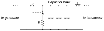
To help decreases the safety risk for technical personnel working on this system, a "discharge" switch is connected in parallel with the capacitor bank to automatically provide a path for discharge current whenever the generator disconnect switch is opened:
|
|
Suppose the capacitor bank consists of forty 1500 mF capacitors connected in parallel (I know the schematic only shows three, but . . .), and the discharge resistor is 10 kW in size. Calculate the amount of time it takes for the capacitor bank to discharge to 10 percent of its original voltage and the amount of time it takes to discharge to 1 percent of its original voltage once the disconnect switch opens and the discharge switch closes.
Time to reach 1% � 46 minutes
Follow-up question: without using the time constant formula again, calculate how long it will take to discharge to 0.1% of its original voltage. How about 0.01%?
Notes:
The follow-up question illustrates an important mathematical principle regarding logarithmic decay functions: for every passing of a fixed time interval, the system decays by the same factor. This is most clearly (and popularly) seen in the concept of half-life for radioactive substances, but it is also seen here for RC (or LR) circuits.
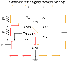
Question 45:
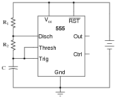
The model "555" integrated circuit is a very popular and useful "chip" used for timing purposes in electronic circuits. The basis for this circuit's timing function is a resistor-capacitor (RC) network:
|
|
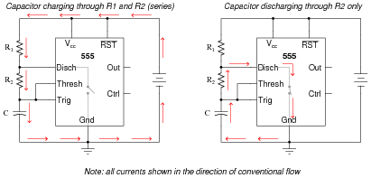
In this configuration, the "555" chip acts as an oscillator: switching back and forth between "high" (full voltage) and "low" (no voltage) output states. The time duration of one of these states is set by the charging action of the capacitor, through both resistors (R1 and R2 in series). The other state's time duration is set by the capacitor discharging through one resistor (R2):
|
|
Obviously, the charging time constant must be tcharge = (R1 + R2)C, while the discharging time constant is tdischarge = R2C. In each of the states, the capacitor is either charging or discharging 50% of the way between its starting and final values (by virtue of how the 555 chip operates), so we know the expression e[(-t)/(t)] = 0.5, or 50 percent.f
Develop two equations for predicting the "charge" time and "discharge" time of this 555 timer circuit, so that anyone designing such a circuit for specific time delays will know what resistor and capacitor values to use.
Footnotes:
f For those who must know why, the 555 timer in this configuration is designed to keep the capacitor voltage cycling between 1/3 of the supply voltage and 2/3 of the supply voltage. So, when the capacitor is charging from 1/3VCC to its (final) value of full supply voltage (VCC), having this charge cycle interrupted at 2/3VCC by the 555 chip constitutes charging to the half-way point, since 2/3 of half-way between 1/3 and 1. When discharging, the capacitor starts at 2/3VCC and is interrupted at 1/3VCC, which again constitutes 50% of the way from where it started to where it was (ultimately) headed.
|
|
Notes:
Although it may seem premature to introduce the 555 timer chip when students are just finishing their study of DC, I wanted to provide a practical application of RC circuits, and also of algebra in generating useful equations. If you deem this question too advanced for your student group, by all means skip it.
Incidentally, I simplified the diagram where I show the capacitor discharging: there is actually another current at work here. Since it wasn't relevant to the problem, I omitted it. However, some students may be adept enough to catch the omission, so I show it here:
|
|
Note that this second current (through the battery) does not go anywhere near the capacitor, and so is irrelevant to the discharge cycle time.
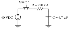
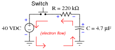
Question 46:
Calculate the rate of change of voltage ([dv/dt]) for the capacitor at the exact instant in time where the switch moves to the "charge" position. Assume that prior to this motion the switch had been left in the "discharge" position for some time:
|
|
Notes:
Some students may think that a rate of change of 4.44 kilovolts per second harbors shock hazard, because, well, 4.44 thousand volts is a lot of voltage! Remind them that this is a rate of change and not an actual voltage figure. This number simply tells us how fast the voltage is changing, not how far it will rise to. It is the difference between saying that a car travels at 75 miles per hour and that a car will travel 75 miles.
Question 47:
Calculate the rate of change of current ([di/dt]) for the inductor at the exact instant in time where the switch moves to the "charge" position.
|
|
Follow-up question: does the resistor value have any effect on this initial [di/dt]? Explain why or why not.
Notes:
Some students may think that a rate of change of 280 amps per second might burn up the wiring, because 280 amps seems like a lot of current. Remind them that this is a rate of change and not an actual current figure. This number simply tells us how fast the current is changing, not how far it will rise to. It is the difference between saying that a car travels at 75 miles per hour and that a car will travel 75 miles.
Question 48:
|
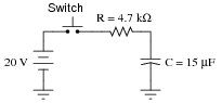
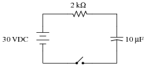
Differential equations may be used to model the charging behavior of an RC circuit. Take, for instance, this simple RC circuit:
|
|
We may develop a loop equation based on Kirchhoff's Voltage Law, knowing that the voltage of the power source is constant (30 volts), and that the voltage drops across the capacitor and resistor are VC = Q/C and VR = IR, respectively:
|
To turn this into a true differential equation, we must express one of the variables as the derivative of the other. In this case, it makes sense to define I as the time-derivative of Q:
|
Show that the specific solution to this differential equation, assuming an initial condition of Q = 0 at t = 0, is as follows:
|
Also, show this solution in a form where it solves for capacitor voltage (VC) instead of capacitor charge (Q).
|
|
|
|
|
|
|
|
|
|
|
|
|
|
|
Given the initial condition that the charge stored in the capacitor is zero (Q = 0) at time zero (t = 0), the constant of integration must be equal to 30C in our specific solution:
|
|
Substituting the given component values into this specific solution gives us the final equation:
|
Showing a final equation in terms of capacitor voltage instead of capacitor charge:
|
|
Notes:
RC time constant circuits are an excellent example of how to apply simple differential equations. In this case, we see that the differential equation is first-order, with separable variables, making it comparatively easy to solve.
It should also be evident to students that any initial condition of capacitor charge may be set into the general solution (by changing the value of the constant).
Question 49:
|
Differential equations may be used to model the charging behavior of an L/R circuit. Take, for instance, this simple L/R circuit:
|
|
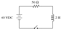
We may develop a loop equation based on Kirchhoff's Voltage Law, knowing that the voltage of the power source is constant (40 volts), and that the voltage drops across the inductor and resistor are VL = L[dI/dt] and VR = IR, respectively:
|
Show that the specific solution to this differential equation, assuming an initial condition of I = 0 at t = 0, is as follows:
|
|
|
|
|
|
|
|
|
|
|
|
|
|
|
Given the initial condition of zero current (I = 0) at time zero (t = 0), the constant of integration must be equal to [40/R] in our specific solution:
|
|
Substituting the given component values into this specific solution gives us the final equation:
|
Notes:
L/R time constant circuits are an excellent example of how to apply simple differential equations. In this case, we see that the differential equation is first-order, with separable variables, making it comparatively easy to solve.
It should also be evident to students that any initial condition for current may be set into the general solution (by changing the value of the constant).
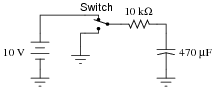
Question 50:
Assume that the switch in this circuit is toggled (switched positions) once every 5 seconds, beginning in the üp" (charge) position at time t = 0, and that the capacitor begins in a fully discharged state at that time. Determine the capacitor voltage at each switch toggle:
|
|
-
Time Switch motion VC (volts)
0 s discharge � charge 0 volts
5 s charge � discharge
10 s discharge � charge
15 s charge � discharge
20 s discharge � charge
25 s charge � discharge
-
Time Switch motion VC (volts)
0 s discharge � charge 0 volts
5 s charge � discharge 6.549 volts
10 s discharge � charge 2.260 volts
15 s charge � discharge 7.329 volts
20 s discharge � charge 2.529 volts
25 s charge � discharge 7.422 volts
Notes:
Be sure to have your students share their problem-solving techniques (how they determined which equation to use, etc.) in class. See how many of them notice that the exponential portion of the equation (e[t/(t)]) is the same for each calculation, and if they find an easy way to manage the calculations by storing charge/discharge percentages in their calculator memories!
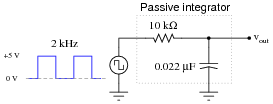
Question 51:
This passive integrator circuit is powered by a square-wave voltage source (oscillating between 0 volts and 5 volts at a frequency of 2 kHz). Determine the output voltage (vout) of the integrator at each instant in time where the square wave transitions (goes from 0 to 5 volts, or from 5 to 0 volts), assuming that the capacitor begins in a fully discharged state at the first transition (from 0 volts to 5 volts):
|
|
-
Transition vout
#1 (0 � 5 volts) 0 volts
#2 (5 � 0 volts)
#3 (0 � 5 volts)
#4 (5 � 0 volts)
#5 (0 � 5 volts)
#6 (5 � 0 volts)
#7 (0 � 5 volts)
#8 (5 � 0 volts)
-
Transition vout
#1 (0 � 5 volts) 0 volts
#2 (5 � 0 volts) 3.395 volts
#3 (0 � 5 volts) 1.090 volts
#4 (5 � 0 volts) 3.745 volts
#5 (0 � 5 volts) 1.202 volts
#6 (5 � 0 volts) 3.781 volts
#7 (0 � 5 volts) 1.214 volts
#8 (5 � 0 volts) 3.785 volts
Challenge question: what are the final (ultimate) values for the integrator output's sawtooth-wave peak voltages?
Notes:
Be sure to have your students share their problem-solving techniques (how they determined which equation to use, etc.) in class. See how many of them notice that the exponential portion of the equation (e[t/(t)]) is the same for each calculation, and if they find an easy way to manage the calculations by storing charge/discharge percentages in their calculator memories!
Question 52:
A 470 mF capacitor begins in a charged state of 270 volts, and discharges through a 100 kW resistor. How long will it take before the capacitor's voltage will fall to a relatively safe value (30 volts or less)?
Notes:
This question incorporates electrical safety into an RC circuit time calculation. Safety is something you should periodically revisit with your students, because it is so important. Ask your students how a ßafe" value of voltage may be determined, and if there are any environmental circumstances impacting this determination.