Basic logic gate troubleshooting
Question 1:
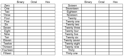
Counting practice: count from zero to thirty-one in binary, octal, and hexadecimal:
|
|
Notes:
In order to familiarize students with these ßtrange" numeration systems, I like to begin each day of digital circuit instruction with counting practice. Students need to be fluent in these numeration systems by the time they are finished studying digital circuits!
One suggestion I give to students to help them see patterns in the count sequences is "pad" the numbers with leading zeroes so that all numbers have the same number of characters. For example, instead of writing "10" for the binary number two, write "00010". This way, the patterns of character cycling (especially binary, where each successively higher-valued bit has half the frequency of the one before it) become more evident to see.
Question 2:
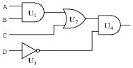
Predict how the operation of this logic gate circuit will be affected as a result of the following faults. Consider each fault independently (i.e. one at a time, no multiple faults):
|
|
- �
- Output of OR gate U2 fails low:
- �
- Output of inverter gate U3 fails low:
- �
- Output of AND gate U1 fails high:
For each of these conditions, explain why the resulting effects will occur.
- �
- Output of OR gate U2 fails low: Gate U4 output stuck in the low state.
- �
- Output of inverter gate U3 fails low: Gate U4 output stuck in the low state.
- �
- Output of AND gate U1 fails high: Gate U4 output simply equal to [`D], no other inputs have any effect on U4's output.
Notes:
The purpose of this question is to approach the domain of circuit troubleshooting from a perspective of knowing what the fault is, rather than only knowing what the symptoms are. Although this is not necessarily a realistic perspective, it helps students build the foundational knowledge necessary to diagnose a faulted circuit from empirical data. Questions such as this should be followed (eventually) by other questions asking students to identify likely faults based on measurements.
Question 3:
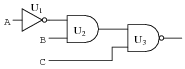
Predict how the operation of this logic gate circuit will be affected as a result of the following faults. Consider each fault independently (i.e. one at a time, no multiple faults):
|
|
- �
- Output of AND gate U2 fails low:
- �
- Output of AND gate U2 fails high:
- �
- Output of inverter gate U1 fails low:
For each of these conditions, explain why the resulting effects will occur.
- �
- Output of AND gate U2 fails low: Gate U3 output stuck in the high state.
- �
- Output of AND gate U2 fails high: Gate U3 output simply equal to [`C], no other inputs have any effect on U3's output.
- �
- Output of inverter gate U1 fails low: Gate U3 output stuck in the high state.
Notes:
The purpose of this question is to approach the domain of circuit troubleshooting from a perspective of knowing what the fault is, rather than only knowing what the symptoms are. Although this is not necessarily a realistic perspective, it helps students build the foundational knowledge necessary to diagnose a faulted circuit from empirical data. Questions such as this should be followed (eventually) by other questions asking students to identify likely faults based on measurements.
Question 4:
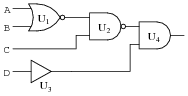
Predict how the operation of this logic gate circuit will be affected as a result of the following faults. Consider each fault independently (i.e. one at a time, no multiple faults):
|
|
- �
- Output of NAND gate U2 fails low:
- �
- Output of buffer gate U3 fails low:
- �
- Output of NOR gate U1 fails high:
For each of these conditions, explain why the resulting effects will occur.
- �
- Output of NAND gate U2 fails low: Gate U4 output stuck in the low state.
- �
- Output of buffer gate U3 fails low: Gate U4 output stuck in the low state.
- �
- Output of NOR gate U1 fails high: Gate U4 output simply equal to [`C]D, no other inputs have any effect on U4's output.
Notes:
The purpose of this question is to approach the domain of circuit troubleshooting from a perspective of knowing what the fault is, rather than only knowing what the symptoms are. Although this is not necessarily a realistic perspective, it helps students build the foundational knowledge necessary to diagnose a faulted circuit from empirical data. Questions such as this should be followed (eventually) by other questions asking students to identify likely faults based on measurements.
Question 5:
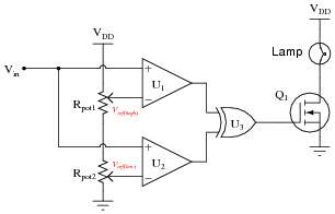
This circuit is supposed to energize a lamp when the input voltage (Vin) falls between the two reference voltages set by Rpot1 and Rpot2. Predict how the operation of this circuit will be affected as a result of the following faults. Consider each fault independently (i.e. one at a time, no multiple faults):
|
|
- �
- Comparator U1 output fails low:
- �
- Comparator U1 output fails high:
- �
- Comparator U2 output fails low:
- �
- Comparator U2 output fails high:
- �
- Wire connecting VDD to Rpot1 fails open:
For each of these conditions, explain why the resulting effects will occur.
- �
- Comparator U1 output fails low: Lamp energizes when Vin > Vref(low), even if Vin > Vref(high).
- �
- Comparator U1 output fails high: Lamp energizes only when Vin < Vref(low).
- �
- Comparator U2 output fails low: Lamp energizes only when Vin > Vref(high).
- �
- Comparator U2 output fails high: Lamp energizes when Vin < Vref(high), even if Vin < Vref(low).
- �
- Wire connecting VDD to Rpot1 fails open: Lamp refuses to energize.
Notes:
The purpose of this question is to approach the domain of circuit troubleshooting from a perspective of knowing what the fault is, rather than only knowing what the symptoms are. Although this is not necessarily a realistic perspective, it helps students build the foundational knowledge necessary to diagnose a faulted circuit from empirical data. Questions such as this should be followed (eventually) by other questions asking students to identify likely faults based on measurements.
Question 6:
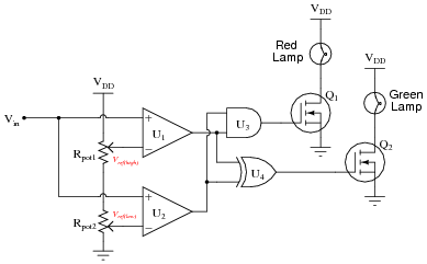
This circuit is supposed to energize the green lamp when the input voltage (Vin) falls between the two reference voltages set by Rpot1 and Rpot2, and energize the red lamp when the input voltage exceeds both reference voltages. However, something is wrong with this circuit: the green lamp operates just as it should, but the red lamp never turns on even when it is supposed to.
|
|
A technician decides to replace the red lamp, thinking it is burned out. This, unfortunately, does not fix the problem. Identify two possible component faults that could account for this problem, and describe what further diagnostic steps you would take to determine the precise nature of the fault.
Notes:
Discuss your students' answers to this question and their troubleshooting strategies. The latter part of the question, where students are asked to explain what they would do next, is the most important part!
Question 7:
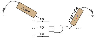
A technician decides to check a suspect three-input AND gate using a logic pulser. She touches the logic pulser to each input of the AND gate, while looking for a pulsing signal at the output with a logic probe.
|
|
No matter which input test point (TP1, TP2, or TP3) she pulses, though, the output test point (TP4) always reads low. Does this prove the AND gate to be defective? Explain why or why not.
Follow-up question: what would have to be checked to make the described test procedure valid?
Notes:
This is a very practical question, as it requires students to carefully consider what a three-input AND gate ought to do under normal conditions, and how to set up a test that is indeed valid.
Question 8:
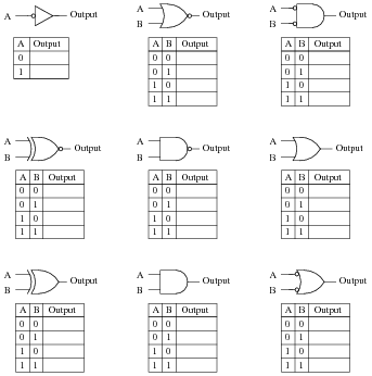
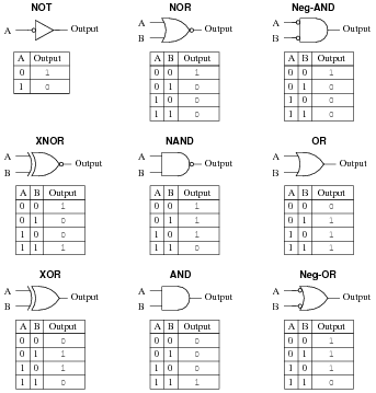
Identify each of these logic gates by name, and complete their respective truth tables:
|
|
|
|
Notes:
In order to familiarize students with the standard logic gate types, I like to given them practice with identification and truth tables each day. Students need to be able to recognize these logic gate types at a glance, or else they will have difficulty analyzing circuits that use them.
Question 9:
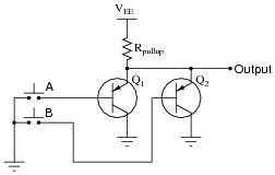
Identify at least two faults in this simple logic gate circuit that could cause its output to fail in the "low" logic state:
|
|
Be sure to explain why the proposed faults would cause the output to fail low.
- �
- Transistor Q1 failed shorted (collector to emitter)
- �
- Transistor Q2 failed shorted (collector to emitter)
- �
- Input line A shorted to ground
- �
- Input line B shorted to ground
- �
- Resistor Rpullup failed open
Follow-up question: though all of these faults would cause the output to go low, not all of them would cause the output to go low in the same way. Explain this.
Notes:
Discuss your students' answers with everyone in class, and their reasoning behind them.
Question 10:
Explain why placing static-sensitive components (such as CMOS integrated circuits) into a block of conductive foam protects them against damage from ESD, and why this protection exists even if the entire block of foam (with chip) is brought to an elevated potential with respect to earth ground.
Notes:
You may underscore this principle by stating to your students that you may walk up to a piece of conductive foam with lots of CMOS chips inserted into it, and touch it with your static-charged finger, with no damage. Even if you draw a spark between your finger and the foam (or any chip pin stuck into the foam), the chips will all be protected because they experience no voltage between their pins.
Question 11:
For a true TTL gate (not high-speed CMOS), what is the default logic state of an input line that is left floating (neither connected to VCC nor Ground)? Explain why this is.
Notes:
The given answer does not provide enough detail to explain why TTL inputs tend to float high, so I recommend you display an internal TTL gate schematic for your students to analyze and comment on in class.
Question 12:
What logic state does a floating CMOS gate input naturally assume? How does this compare against traditional TTL?
Follow-up question: what state does a floating input assume for a high-speed CMOS (74HCxx) logic gate, which is designed to be an upgrade/replacement for traditional TTL gates?
Notes:
Ask your students to explain their answer based on an analysis of the internals of a CMOS gate, versus the internals of a TTL gate. Memorization is not good enough - students must grasp why these different logic families behave as they do.
Question 13:
As an electronics instructor, I have the opportunity to see a lot of creative mistakes made by students as they learn to build circuits. One very common mistake made in CMOS circuit construction manifests itself in erratic behavior: the circuit may function correctly for a time, but suddenly and randomly it stops. Then, just by waving your hand next to the circuit, it begins to work again!
This problem is especially prevalent on days where the atmospheric humidity is low, and static electric charges easily accumulate on objects and people. Explain what sort of CMOS wiring mistake would cause a powered logic gate to behave erratically due to nearby static electric fields, and what the proper solution is to this problem.
Notes:
Students think I'm a wizard by being able to troubleshoot their CMOS circuits just by waving my hand next to them. No, I'm just wise in the ways of common student error!
Question 14:
Explain why the allowable power supply voltage range for a true TTL (not high-speed CMOS) logic gate is so narrow. What is the typical range of supply voltages for a true TTL gate, and why can't this type of logic gate operate from a wider range of voltages as CMOS gates can?
Notes:
Many of the old 74xx and 74LSxx logic circuits are considered obsolete, but may still be found in a lot of operating equipment! It is not uncommon to have students mistakenly research the datasheets of a newer logic family such as 74HCxx which has different power supply requirements than traditional TTL. Be prepared to elaborate on the difference(s) between these IC families if and when your students encounter this confusion!
Question 15:
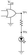
Logic probes are useful tools for troubleshooting digital logic gate circuits, but they certainly have limitations. For instance, in this simple circuit, a logic probe will give correct "high" and "low" readings at test point 1 (TP1), but it will always read "low" (even when the LED is on) at test point 2 (TP2):
|
|
Now, obviously the output of the gate is "high" when the LED is on, otherwise it would not receive enough voltage to illuminate. Why then does a logic probe fail to indicate a high logic state at TP2?
Follow-up question: this LED circuit is rather simple, and the scenario almost silly, because the LED's presence makes checking the logic state at TP1 and TP2 superfluous! Can you think of any other circuit or situation where a similar false reading may be displayed by a logic probe - where the logic state has not been made visually obvious by the presence of an LED?
Notes:
It is easy for students to overlook the limitations of a logic probe, and to forget what actually drives it to say "high" or "low" when measuring a logic level. This is why in low-speed circuits I prefer to use a good digital voltmeter rather than a logic probe to discern logic states. With a voltmeter, you can see exactly what the voltage level is, and determine whether or not the logic state is marginal.
Question 16:
A useful test instrument for digital gate circuit troubleshooting is a logic pulser. Explain what one is and give an example of how it is used.
Notes:
Students may wonder how a logic pulser is able to override the output state of any gate it's connected to. The answer has to do with the brief time that a pulser operates, and also the pulser's low impedance (compared to the relatively high impedance of the overridden gate output).
Question 17:
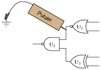
A technician is using a logic pulser to force the logic state of the wire connecting two of the gates together:
|
|
Which gate, or gates, are we testing by placing the pulser in this position? What other instrument(s) would we have to connect to the circuit (and where?) to complete the test? Why does the logic pulser require a ground connection to do its job in this circuit?
The pulser requires a ground connection so it may drive current into or out of the circuit under test. Without a ground connection, there would be no complete path for current, and the pulser would not be able to överride" the output state of the NOR gate.
Follow-up question: what logic state should the other input of the NAND gate be in for this test? Explain why.
Notes:
The point I am trying to convey with this question is that forcing a gate's output high or low with a logic pulser tells us nothing about that gate. We use a pulser to override gate outputs in order to test the function of gates receiving that signal. In other words, we use a pulser to test gates "downstream" of where the pulser contacts the circuit.
Question 18:
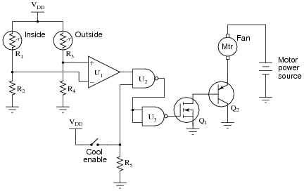
In this circuit, a comparator is set up to detect whether the outside or inside temperature is greater, and turns on a cooling fan when conditions are right. Predict how the operation of this circuit will be affected as a result of the following faults. Consider each fault independently (i.e. one at a time, no multiple faults):
|
|
- �
- Comparator U1 output fails low:
- �
- NAND gate U2 output fails low:
- �
- NAND gate U2 output fails high:
- �
- Transistor Q1 fails shorted (drain to source):
- �
- Resistor R2 fails open:
- �
- Thermistor R3 fails open:
- �
- Resistor R4 fails open:
- �
- Solder bridge (short) across thermistor R1:
- �
- Comparator U1 output fails low: Fan never turns on.
- �
- NAND gate U2 output fails low: Fan always remains on.
- �
- NAND gate U2 output fails high: Fan never turns on.
- �
- Transistor Q1 fails shorted (drain to source): Fan always remains on.
- �
- Resistor R2 fails open: Fan never turns on.
- �
- Thermistor R3 fails open: Fan never turns on.
- �
- Resistor R4 fails open: Fan always remains on.
- �
- Solder bridge (short) across thermistor R1: Fan never turns on.
Follow-up question: does Q1 source or sink current? What about Q2?
Notes:
Questions like this help students hone their troubleshooting skills by forcing them to think through the consequences of each possibility. This is an essential step in troubleshooting, and it requires a firm understanding of circuit function.
Question 19:
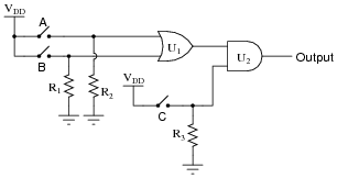
The output of the following gate circuit is always low, no matter what states the input switches are in. Assume that CMOS logic gates are being used here:
|
|
Identify which of these possibilities could account for the output always being low:
- �
- Output of U1 stuck in a high state
- �
- Output of U1 stuck in a low state
- �
- R1 failed open
- �
- Switch C failed open
- �
- Switch B failed open
- �
- Switch A failed shorted
- �
- Output of U1 stuck in a low state
- �
- Switch C failed open
Follow-up question: determine what each of the other faults would do to the circuit.
Notes:
Questions like this help students hone their troubleshooting skills by forcing them to think through the consequences of each possibility. This is an essential step in troubleshooting, and it requires a firm understanding of circuit function.
If a student suggests switch B failing open could cause the output to remain low, they are either misunderstanding the operation of an OR gate, or they are assuming switch A has also failed open (or something else happening that keeps input A low all the time). I find this kind of assumption frequently in students new to troubleshooting: assuming multiple faults. While multiple faults are not impossible, they are less likely than single faults. Therefore, the good technician first looks for single faults capable of accounting for all observed states before looking for (less likely) combinations of faults. This is a practical application of Occam's Razor.
Question 20:
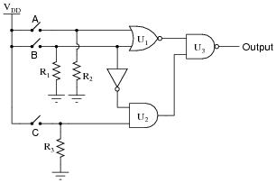
The output of the following gate circuit is always high, no matter what states the input switches are in. Assume that CMOS logic gates are being used here:
|
|
Identify which of these possibilities could account for the output always being high:
- �
- Output of U1 stuck in a high state
- �
- Output of U2 stuck in a high state
- �
- R1 failed open
- �
- R2 failed shorted
- �
- R3 failed shorted
- �
- Switch A failed open
- �
- Switch B failed shorted
- �
- Switch C failed shorted
- �
- R1 failed open
- �
- R3 failed shorted
- �
- Switch B failed shorted
Notes:
Questions like this help students hone their troubleshooting skills by forcing them to think through the consequences of each possibility. This is an essential step in troubleshooting, and it requires a firm understanding of circuit function.
Question 21:
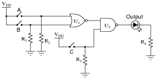
The following gate circuit has a problem:
|
|
When tested, it is found that the circuit does not respond in the same manner as its (ideal) truth table predicts. Here is a comparison of the ideal and actual truth tables, as predicted and tested:
-
A B C Output (ideal) Output (actual)
0 0 0 1 1
0 0 1 0 0
0 1 0 1 1
0 1 1 1 0
1 0 0 1 1
1 0 1 1 1
1 1 0 1 1
1 1 1 1 1
The first thing a good electronics technician would do, of course, is set up either a voltmeter or a logic probe and begin testing for logic levels in the circuit to see what is wrong. However, the settings of the input switches are very important as part of the diagnosis. Based on the design of the circuit, and the truth table results shown, in what states (open or closed) would you first set the input switches, and then what logic level would you first test with the logic probe or voltmeter?
- �
- A open (0)
- �
- B closed (1)
- �
- C closed (1)
Then, measure the logic state of the lower input on the NOR gate (coming from the "B" switch).
Notes:
Ask your students to explain what logic state is supposed to be at that point in the circuit, and what logic state they suspect might be there that could account for the aberrant output. Also discuss why this particular choice of switch settings is the best for a first test.
If students do not immediately grasp why the switches should be set as the answer indicates, pose the following scenario. Suppose they were asked to troubleshoot a simple light bulb circuit using only a voltmeter. The problem is, the light bulb does not come on when the switch is closed. Would it be best to proceed with their voltage measurements with the switch on or off? It should be easy to understand that having the switch in the off position would only interfere with the diagnosis, and that turning the switch on is the best way to reveal the fault (so that one could use the voltmeter to see where voltage is not present, but should be). Likewise, it is wise to set up this faulted logic circuit in such a way that the output ought to be doing something it isn't. This way, one may easily compare logic states as they are versus as they should be, and from there determine what type of fault could be causing the problem.
Question 22:
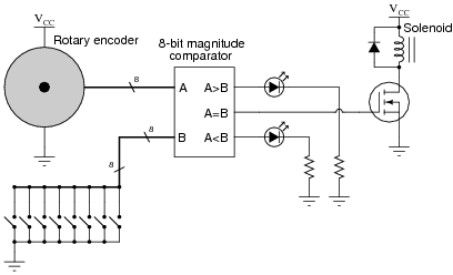
The purpose of this circuit is to provide indication of when the rotary encoder shaft is in a particular position (matching the setting of the 8-position switch array):
|
|
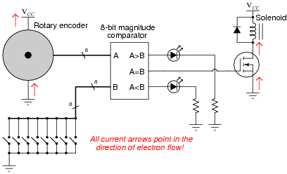
Trace the directions of all currents in this circuit, using electron flow notation, when the encoder position matches the pre-set code entered at the switches. Then, identify specific component failures that could result in the solenoid coil not energizing in this condition.
|
|
Potential component faults resulting in non-energization of solenoid:
- �
- MOSFET failed open (drain-to-source)
- �
- Broken wire between MOSFET drain and solenoid coil
- �
- Loss of power (VCC) to comparator circuit
- �
- Loss of power to encoder (only if switch code is not 0000 0000)
Notes:
Discuss fault options with your students, asking them to explain why each proposed fault would result in the solenoid not energizing.