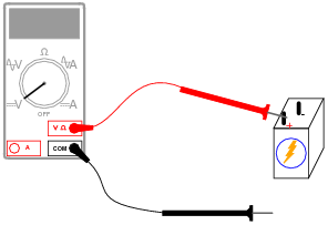
Basic voltmeter use
Question 1:
What will this voltmeter register when connected to a battery as shown (assume a battery voltage of 6 volts)? Explain your answer.
|
|
Follow-up question: what does this tell you about the nature of voltage, and how it is measured?
Notes:
This question affords an excellent opportunity to discuss another foundational concept of electricity: that voltage is always measured between two points.
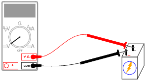
Question 2:
What will this voltmeter register when connected to a battery as shown (assume a battery voltage of 6 volts)? Explain your answer.
|
|
What do you suppose will happen if the voltmeter is of the analog style (with a moving "needle" rather than a numerical display)?
Notes:
Ask the students how an analog (moving pointer) style of voltmeter would respond in this situation. This question lends itself very well to simple experimentation in the classroom, even during discussion time.
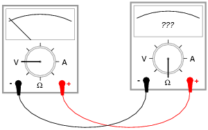
Question 3:
If we were to connect a voltmeter directly to an ohmmeter, what would you expect to see the ohmmeter register, for resistance between its test leads?
|
|
Notes:
Ask your students why a voltmeter should have a very high resistance (many thousands or millions of ohms) between its test leads. How does this property of all voltmeters relate to how they are used to measured current in real circuits?
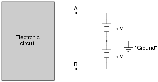
Question 4:
Many electronic circuits use what is called a split or a dual power supply:
|
|
Determine what a digital voltmeter would indicate if connected between the following points:
- �
- Red lead on Ä", black lead on ground
- �
- Red lead on "B", black lead on ground
- �
- Red lead on Ä", black lead on "B"
- �
- Red lead on "B", black lead on Ä"
NOTE: in electronic systems, "ground" is often not associated with an actual earth-soil contact. It usually only refers to a common point of reference somewhere in the circuit used to take voltage measurements. This allows us to specify voltages at single points in the circuit, with the implication that "ground" is the other point for the voltmeter to connect to.
- �
- Red lead on Ä", black lead on ground (Digital voltmeter reads +15 volts)
- �
- Red lead on "B", black lead on ground (Digital voltmeter reads -15 volts)
- �
- Red lead on Ä", black lead on "B" (Digital voltmeter reads +30 volts)
- �
- Red lead on "B", black lead on Ä" (Digital voltmeter reads -30 volts)
Notes:
This question may be easily answered with only a voltmeter, two batteries, and a single "jumper" wire to connect the two batteries in series. It does not matter if the batteries are 15 volts each! The fundamental principle may still be investigated with batteries of any voltage, so this is a very easy demonstration to set up during discussion time.
Question 5:
Determine how much voltage a voltmeter would indicate when connected between the following points in this circuit:
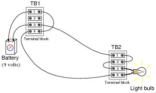
|
|
- �
- Between TB1-1 and TB1-3
- �
- Between TB1-4 and TB2-4
- �
- Between TB2-3 and TB2-1
- �
- Between TB1-1 and TB2-1
Hint: it might help to draw a neat schematic diagram of this circuit first, with all connection points labeled!
- �
- Between TB1-1 and TB1-3 (Voltmeter measures 9 volts)
- �
- Between TB1-4 and TB2-4 (Voltmeter measures 0 volts)
- �
- Between TB2-3 and TB2-1 (Voltmeter measures 0 volts)
- �
- Between TB1-1 and TB2-1 (Voltmeter measures 9 volts)
Notes:
This question provides an opportunity to discuss the concept of electrically common points: namely, that there can be no substantial voltage built up between points that are made ëlectrically common" by means of low-resistance connections between them.
This is also an opportunity to develop the skill of drawing a schematic diagram for a real-life circuit. Schematic diagrams, of course, are very helpful in that they provide a nice, neat layout of all circuit components, making visualization of voltage drops and other quantities easier.
Question 6:
Determine how much voltage a voltmeter would indicate when connected between the following points in this faulted circuit:
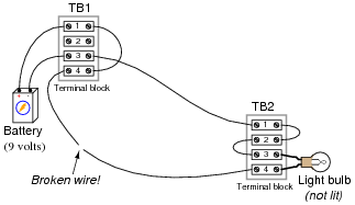
|
|
- �
- Between TB1-1 and TB1-3
- �
- Between TB1-4 and TB2-4
- �
- Between TB2-3 and TB2-1
- �
- Between TB1-1 and TB2-1
Hint: it might help to draw a neat schematic diagram of this circuit first, with all connection points labeled!
- �
- Between TB1-1 and TB1-3 (Voltmeter measures 9 volts)
- �
- Between TB1-4 and TB2-4 (Voltmeter measures 9 volts)
- �
- Between TB2-3 and TB2-1 (Voltmeter measures 0 volts)
- �
- Between TB1-1 and TB2-1 (Voltmeter measures 9 volts)
Notes:
Ask your students this question: how does the break in the wire affect electrical "commonality" between TB1-4 and TB2-4?
Question 7:
Determine what these four voltmeters (A, B, C, D) will register when connected to this circuit in the following positions (assume a battery voltage of 6 volts):
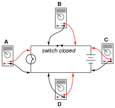
|
|
- �
- Voltmeter A =
- �
- Voltmeter B =
- �
- Voltmeter C =
- �
- Voltmeter D =
- �
- Voltmeter A = 6 volts
- �
- Voltmeter B = 0 volts
- �
- Voltmeter C = 6 volts
- �
- Voltmeter D = 0 volts
Notes:
Students often find the terms öpen" and "closed" to be confusing with reference to electrical switches, because they sound opposite to the function of a door (i.e. you can only go through an open door, but electricity can only go through a closed switch!). The words actually make sense, though, if you look at the schematic symbol for an electrical switch as a door mounted ßideways" in the circuit. At least visually, then, öpen" and "closed" will have common references.
One analogy to use for the switch's function that makes sense with the schematic is a drawbridge: when the bridge is down (closed), cars may cross; when the bridge is up (open), cars cannot.
I have found that the concept of electrically common points is most helpful when students first learn to relate voltage drop with continuity (breaks or non-breaks) in a circuit.
To be able to immediately relate the expected voltage drop between two points with the electrical continuity between those points is a very important foundational skill in electrical troubleshooting. Without mastery of this skill, students will have great difficulty detecting and correcting faults in circuits caused by poor connections and broken wires, which constitute a fair portion of realistic circuit failures.
Question 8:
Determine what these four voltmeters (A, B, C, D) will register when connected to this circuit in the following positions (assume a battery voltage of 6 volts):
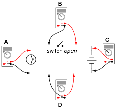
|
|
- �
- Voltmeter A =
- �
- Voltmeter B =
- �
- Voltmeter C =
- �
- Voltmeter D =
- �
- Voltmeter A = 0 volts
- �
- Voltmeter B = 6 volts
- �
- Voltmeter C = 6 volts
- �
- Voltmeter D = 0 volts
Notes:
Students often find the terms öpen" and "closed" to be confusing with reference to electrical switches, because they sound opposite to the function of a door (i.e. you can only go through an open door, but electricity can only go through a closed switch!). The words actually make sense, though, if you look at the schematic symbol for an electrical switch as a door mounted ßideways" in the circuit. At least visually, then, öpen" and "closed" will have common references.
One analogy to use for the switch's function that makes sense with the schematic is a drawbridge: when the bridge is down (closed), cars may cross; when the bridge is up (open), cars cannot.
I have found that the concept of electrically common points is most helpful when students first learn to relate voltage drop with continuity (breaks or non-breaks) in a circuit.
To be able to immediately relate the expected voltage drop between two points with the electrical continuity between those points is a very important foundational skill in electrical troubleshooting. Without mastery of this skill, students will have great difficulty detecting and correcting faults in circuits caused by poor connections and broken wires, which constitute a fair portion of realistic circuit failures.
Question 9:
Shown here is a circuit constructed on a PCB (a "Printed Circuit Board"), with copper "traces" serving as wires to connect the components together:
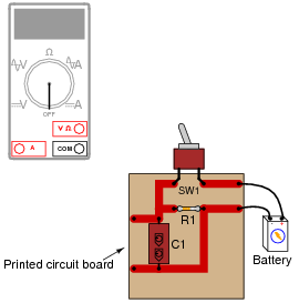
|
|
How would the multimeter be used to measure the voltage across the component labeled "R1" when energized? Include these important points in your answer:
- �
- The configuration of the multimeter (selector switch position, test lead jacks)
- �
- The connections of the meter test leads to the circuit
- �
- The state of the switch on the PCB (open or closed)
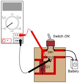
|
|
The test lead connections (to the circuit) shown are not the only correct answer. It is possible to touch the test leads to different points on the PCB and still measure the voltage across the resistor (component labeled R1). What are some alternative points on the PCB where the voltage across R1 could be measured?
Notes:
Many multimeters use ïnternational" symbols to label DC and AC selector switch positions. It is important for students to understand what these symbols mean.
The test lead connections (to the circuit) shown are not the only correct answer. It is possible to touch the test leads to different points on the PCB and still measure the voltage across the resistor (R1). However, if there are poor connections on the circuit board (between component leads and copper traces), measuring voltage at points on the circuit board other than directly across the component in question may give misleading measurements. Discuss this with your students.
Question 10:
Suppose I were about to measure an unknown voltage with a manual-range voltmeter. This particular voltmeter has several different voltage measurement ranges to choose from:
- �
- 500 volts
- �
- 250 volts
- �
- 100 volts
- �
- 50 volts
- �
- 25 volts
- �
- 10 volts
- �
- 5 volts
What range would be best to begin with, when first measuring this unknown voltage with the meter? Explain your answer.
Notes:
I always like to have my students begin their test equipment familiarity by using old-fashioned analog multimeters. Only after they have learned to be proficient with an inexpensive meter do I allow them to use anything better (digital, auto-ranging) in their work. This forces students to appreciate what a "fancy" meter does for them, as well as teach them basic principles of instrument ranging and measurement precision.
Question 11:
Suppose I needed to test for the presence of DC voltage between all wires connected to this terminal block. What is the fewest number of individual measurements I would have to perform with with a voltmeter in order to test for voltage between all possible wire pair combinations (remember that voltage is always measured between two points!)?
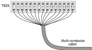
|
|
|
Where,
n = The number of wires
Challenge question: there is a way to mathematically reduce the expression shown above so that it only contains the variable n, and not i or the ßummation" symbol (�).
Notes:
This is an interesting mathematical exercise, to determine the total number of 2-wire combinations resulting from 15 wires. If your students have difficulty determining this number, suggest they try to figure out the total number of 2-wire combinations with a smaller quantity of wires, say four instead of fifteen.
Incidentally, this is a powerful problem-solving technique: simplify the problem into one with smaller quantities, until the solution becomes intuitively obvious, then determine the precise steps needed to arrive at that obvious solution. After that, apply those same steps to the original problem.
The challenge question is actually pre-calculus or calculus level.
Question 12:
Voltmeters must be connected in parallel with the voltage to be measured:
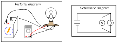
|
|
In order to practically function, an voltmeter must have some finite amount of internal resistance. It is usually a very large amount, but less than infinite. It should be apparent to you that the presence of this resistance will have some effect on the circuit voltage, when compared to the amount of voltage in the circuit without any meter connected, due to the fact that real voltage sources tend to "sag" when subjected to additional loads:
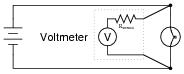
|
|
Explain why it is usually safe to ignore the internal resistance of an voltmeter, though, when it is in a circuit. A common term used in electrical engineering to describe this intentional oversight is swamping. In this particular circuit an engineer would say, "The resistance of the light bulb swamps the internal resistance of the voltmeter."
Notes:
I have found that the concept of "swamping" is extremely useful when making estimations. To be able to ignore the values of some components allows one to simplify a great many circuits, enabling easier calculations to be performed.