

Radio Modifications, Problems, Hints and Tips


Pro-2010 Discriminator Output added:
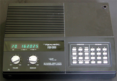
It's fairly simple to equip the Realistic PRO-2010 with a discriminator output.
The interior of the scanner is spacious, and DIL IC's are used.
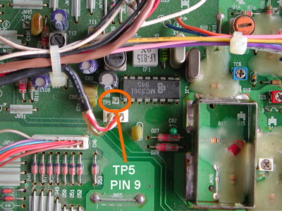
The receiver IC is a 10420. The unfiltered audio can be found on pin 9 and on
test point TP-5, so no soldering to the IC is required..
TP5 consists of a vertically mounted, unmarked 0 Ohm resistor. A 10K resistor is
connected to TP5. The other lead of the 10 k resistor is connected to piece of
shielded wire. The braid of this wire can be connected to the shield of a coil
close to the receiver IC.
The other side of the shielded wire is connected to a 3.5 mm jack that can be
mounted in the side panel of the scanner.
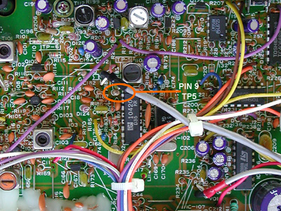 Pin 9 and TP5 contain the base band signal
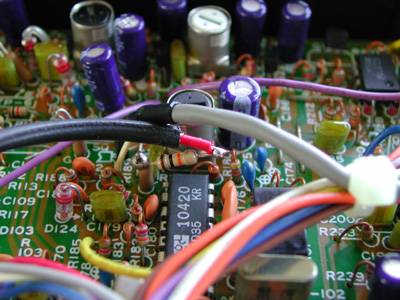 A 10K resistor, soldered to TP5
--------------------------------------------------------------------------------
A 10K resistor, soldered to TP5
--------------------------------------------------------------------------------
 Cellular Restoration for the Realistic Pro-2022 Scanner.
The Realistic PRO-2022 certainly is a look-alike for the all-time popular,
but now-discontinued, PRO-2005. But is the similarity only cosmetic? What tricks
can be done to increase the utility of the lower-cost 2022? Of the greatest
interest, can cell-phone coverage, censored at the factory, be restored? Yes!
After removing the two upper back screws and the top lid, locate the black cable
just behind the front panel. Adjacent to the cable are four diodes locations:
D42, D43, D44 and D45.
D42
is not present; installed, it adds the 68-88 Mhz European mid band (which
includes the US 76-82 MHz mid band), removing the US 30-54 MHz low band.
Even if a switch were installed to allow the diode to be selected, additional
components and realignment are necessary for that higher frequency coverage.
Don't do it!
D43
is present, allowing the 800 MHz band to be received; the diode may be deleted
so that the same microprocessor may be used in scanner models which don't have
that 800 MHz capability. Don't touch it!
D44
is present, deleting the cellular mobile and base frequencies. If one lead is
cut, total 806-960 frequency is restored, including 30 kHz steps in the cellular
band. Keep in mind, however, that mobile telephone eavesdropping is prohibited
by the Electronic Communications Privacy Act!
This modification may void your warranty it is best to cut the lead carefully,
gently separating the gap slightly so that it may be resoldered in case the
radio needs warranty repair later.
D45
is not present; installed, it makes the cellular 30 kHz increments change to
12.5 kHz. A small SPST switch connected in series with one lead of a 1N914 or
1N4148 could allow selection of the 25 kHz step interval in those areas which
utilize that channel spacing.
To do this, it is necessary to unsolder a shield under the circuit board which
covers the solder pads for the diodes. Such a modification should only be
attempted by someone familiar with electronic circuitry.
Mods for the discriminator:
There is a growing interest in tapping the discriminator audio out of various
scanners for decoding a variety of signals, (including: CTCSS, POCSAG, DTMF
tones, RTTY, FAX, AIS, ETC. By and large, such signals *cannot* be taken
directly from TAPE REC jacks, headphone jacks and EXT SPEAKER jacks because of
the voice-band filtering that is done between the signal source and these output
jacks. So, not a good thing.
Therefore, it is necessary to tap directly to the output of the discriminator
chip in your scanner. For the Pro-2022 it is pin 9/TP5 on the MC3361(x).
Cellular Restoration for the Realistic Pro-2022 Scanner.
The Realistic PRO-2022 certainly is a look-alike for the all-time popular,
but now-discontinued, PRO-2005. But is the similarity only cosmetic? What tricks
can be done to increase the utility of the lower-cost 2022? Of the greatest
interest, can cell-phone coverage, censored at the factory, be restored? Yes!
After removing the two upper back screws and the top lid, locate the black cable
just behind the front panel. Adjacent to the cable are four diodes locations:
D42, D43, D44 and D45.
D42
is not present; installed, it adds the 68-88 Mhz European mid band (which
includes the US 76-82 MHz mid band), removing the US 30-54 MHz low band.
Even if a switch were installed to allow the diode to be selected, additional
components and realignment are necessary for that higher frequency coverage.
Don't do it!
D43
is present, allowing the 800 MHz band to be received; the diode may be deleted
so that the same microprocessor may be used in scanner models which don't have
that 800 MHz capability. Don't touch it!
D44
is present, deleting the cellular mobile and base frequencies. If one lead is
cut, total 806-960 frequency is restored, including 30 kHz steps in the cellular
band. Keep in mind, however, that mobile telephone eavesdropping is prohibited
by the Electronic Communications Privacy Act!
This modification may void your warranty it is best to cut the lead carefully,
gently separating the gap slightly so that it may be resoldered in case the
radio needs warranty repair later.
D45
is not present; installed, it makes the cellular 30 kHz increments change to
12.5 kHz. A small SPST switch connected in series with one lead of a 1N914 or
1N4148 could allow selection of the 25 kHz step interval in those areas which
utilize that channel spacing.
To do this, it is necessary to unsolder a shield under the circuit board which
covers the solder pads for the diodes. Such a modification should only be
attempted by someone familiar with electronic circuitry.
Mods for the discriminator:
There is a growing interest in tapping the discriminator audio out of various
scanners for decoding a variety of signals, (including: CTCSS, POCSAG, DTMF
tones, RTTY, FAX, AIS, ETC. By and large, such signals *cannot* be taken
directly from TAPE REC jacks, headphone jacks and EXT SPEAKER jacks because of
the voice-band filtering that is done between the signal source and these output
jacks. So, not a good thing.
Therefore, it is necessary to tap directly to the output of the discriminator
chip in your scanner. For the Pro-2022 it is pin 9/TP5 on the MC3361(x).
Solder a 10K resistor to TP5. Pin 9/TP5 contain the unfiltered audio.
Solder a 2.2 nF capacitor from the resistor's other lead to ground, e.g. to
the metal case of the IF coil.
Connect a short strand of wire to the junction of the resistor and capacitor.
Mount a 3.5 mm chassis socket in the back of the scanner. Connect the wire
with the inner contact. Since the back plane is grounded, there's no need to
connect the socket's ground lug.
 Pin 9 and TP5 with the unfiltered audio
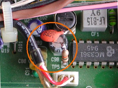 Connection of 10K and 2.2nF capacitor
Improving Squelch for PRO-2022:
Connection of 10K and 2.2nF capacitor
Improving Squelch for PRO-2022:
Replace resistor R91(33K) with a 220K type, chip, 1/10W, 5%, to improve the
squelch sensitivity. MFR's Part No. RCM224J55, Sayal Electronics, etc.
--------------------------------------------------------------------------------
 Kenwood TS850 Power Distribution Problem
Power on the Kenwood TS850 was measured a bit unstable during transmit.
A deviation of 0.5V at 20A was measured at 13.8V (14V). This is 10watts lost,
probably somewhere in the fuse section. No definitive answer or fix for it at
this time (see below for more info).
-------------------------------------------------------
COMMENTS on the TS850:
There are still some problems with the electrolytic capacitors on the carrier
board, on the display board, some of them near the audio section and the battery
that has to be changed.
Don't wait for those components to leak! Change them before they ruin your rig.
About the first DDS chips and they're failure. I don't know if the chips are the
problem or the bad SMD electrolytic capacitors.
The first thing after I got this rig was to take off the cover and see if there
something wrong and what do you think? On the carrier board near a capacitor
there was electrolytic juice. He didn't do any damage yet but was close.
Once again, if you didn't change those parts and you rig is still working, DON'T
WAIT for the problems to happen.
Ah by the way, this rig function great on 14V. If you experience the classic
ALC problem check the voltage on the power supply and on the rig, near
the connector. Don't let it drop under those 14V.
All the best from my side! 73's YO3IBW Dan.
--------------------------------------------------------
I purchased one new in the 80's. Loved it. I sold it after the display went out.
I bought a used one about a two years ago. After three months-the display went
out on that one. After reading some of the very fine web articles describing
replacement of the troublesome caps, I took that repair on. I replaced two caps
and also repaired the trace that had corroded. It worked for another six months
and the display died, again. I guess I would recommend as a back up rig, if you
have the desire to bench it as it will fail.
--------------------------------------------------------
I wouldn't part with my 850 for anything but I understand one day it will die.
After serving me for 16+ years I won't feel bad. My other rig (Ten-Tec Jupiter)
I think is as good but once the 850 says "73" for the last time I'll honor it by
purchasing the only rig on the market I would be willing to spend my money on
nowadays - a Ten-Tec Omni VII.
--------------------------------------------------------
I had many radios thru out time, always looking for the new thing, but sometimes
new do not mean the best from Icom to Yaesu I try them new and old, Kenwood on
the other hand I never care for, until I meet my new friend Mr.TS850S and what
can I say, is the best audio I ever hear. The easiest radio to get that
imposible QSO without wasting time trying to figure out how to operate the rig,
every pile up just 100w in the first call they come back always and the audio
reports from those stations are always super, i dont know why i didnt get one
of these a long time ago is amazing and I'm super happy with it. I mean whats
better a young wine or an award wining vintage wine--73's
--------------------------------------------------------
My very first HF Rig was a Kenwood TS 850SAT and wanting to see what other items
on the market i sold it after a year or so. That was twelve years ago and today
at the Warminster Hamfest I bought my second one. It works like new, with a pair
of 500 hertz filters installed this rig is sweet. And the price less than 600.00
with the autotuner and a mc60. Not much else to say as we all know by now how
well the 850 works. So if you come across one at a hamfest or ?? do not pass it
up... Ted
--------------------------------------------------------
RELAY SPEED-UP
(Increasing relay speed)
Kenwood TS850 Power Distribution Problem
Power on the Kenwood TS850 was measured a bit unstable during transmit.
A deviation of 0.5V at 20A was measured at 13.8V (14V). This is 10watts lost,
probably somewhere in the fuse section. No definitive answer or fix for it at
this time (see below for more info).
-------------------------------------------------------
COMMENTS on the TS850:
There are still some problems with the electrolytic capacitors on the carrier
board, on the display board, some of them near the audio section and the battery
that has to be changed.
Don't wait for those components to leak! Change them before they ruin your rig.
About the first DDS chips and they're failure. I don't know if the chips are the
problem or the bad SMD electrolytic capacitors.
The first thing after I got this rig was to take off the cover and see if there
something wrong and what do you think? On the carrier board near a capacitor
there was electrolytic juice. He didn't do any damage yet but was close.
Once again, if you didn't change those parts and you rig is still working, DON'T
WAIT for the problems to happen.
Ah by the way, this rig function great on 14V. If you experience the classic
ALC problem check the voltage on the power supply and on the rig, near
the connector. Don't let it drop under those 14V.
All the best from my side! 73's YO3IBW Dan.
--------------------------------------------------------
I purchased one new in the 80's. Loved it. I sold it after the display went out.
I bought a used one about a two years ago. After three months-the display went
out on that one. After reading some of the very fine web articles describing
replacement of the troublesome caps, I took that repair on. I replaced two caps
and also repaired the trace that had corroded. It worked for another six months
and the display died, again. I guess I would recommend as a back up rig, if you
have the desire to bench it as it will fail.
--------------------------------------------------------
I wouldn't part with my 850 for anything but I understand one day it will die.
After serving me for 16+ years I won't feel bad. My other rig (Ten-Tec Jupiter)
I think is as good but once the 850 says "73" for the last time I'll honor it by
purchasing the only rig on the market I would be willing to spend my money on
nowadays - a Ten-Tec Omni VII.
--------------------------------------------------------
I had many radios thru out time, always looking for the new thing, but sometimes
new do not mean the best from Icom to Yaesu I try them new and old, Kenwood on
the other hand I never care for, until I meet my new friend Mr.TS850S and what
can I say, is the best audio I ever hear. The easiest radio to get that
imposible QSO without wasting time trying to figure out how to operate the rig,
every pile up just 100w in the first call they come back always and the audio
reports from those stations are always super, i dont know why i didnt get one
of these a long time ago is amazing and I'm super happy with it. I mean whats
better a young wine or an award wining vintage wine--73's
--------------------------------------------------------
My very first HF Rig was a Kenwood TS 850SAT and wanting to see what other items
on the market i sold it after a year or so. That was twelve years ago and today
at the Warminster Hamfest I bought my second one. It works like new, with a pair
of 500 hertz filters installed this rig is sweet. And the price less than 600.00
with the autotuner and a mc60. Not much else to say as we all know by now how
well the 850 works. So if you come across one at a hamfest or ?? do not pass it
up... Ted
--------------------------------------------------------
RELAY SPEED-UP
(Increasing relay speed)
 This in many magazines published simple design for increasing the relay speed is
often overlooked. The circuit speeds the relay by momentarily doubling the
normal supply voltage and I added the gadget in a Ten Tec Corsair II and a
linear (home brewed) amplifiers for speeding-up the T/R relays.
On receive the capacitor is charged to the supply voltage through both diodes.
When the switch (PTT) is pushed, the transistor turns on through 1 kΩ by
the charged capacitor. Then the relay momentarily is supplied with twice its
voltage and closes faster than normal without harming the coil. As soon as the
capacitor discharges, the relay coil sees a normal supply voltage.
The TS-850S Repair Page
This in many magazines published simple design for increasing the relay speed is
often overlooked. The circuit speeds the relay by momentarily doubling the
normal supply voltage and I added the gadget in a Ten Tec Corsair II and a
linear (home brewed) amplifiers for speeding-up the T/R relays.
On receive the capacitor is charged to the supply voltage through both diodes.
When the switch (PTT) is pushed, the transistor turns on through 1 kΩ by
the charged capacitor. Then the relay momentarily is supplied with twice its
voltage and closes faster than normal without harming the coil. As soon as the
capacitor discharges, the relay coil sees a normal supply voltage.
The TS-850S Repair Page
TH6 balun replacement project
Basic Programming for the Uniden BC346XT Scanner
Yaesu FT-60R modifications