Home » Circuits
Audible Flasher Warning
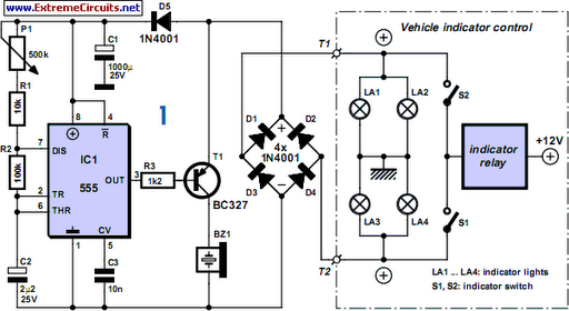
If you’re a biker or scooter rider you’ll know how easy it is to forget to cancel your flashing indicators after turning without an audible reminder. Constantly glancing at indicator lamps is hardly an option; your eyes should be on the road ahead! The simple circuit shown here provides an audible reminder. The clever bit is the way it doesn’t annoy you by beeping the instant you activate the flashers but only after a preset time, in other words when your indicators are active longer than normal. Supply to the circuit is through the flasher relay.With the indicators activated a squarewave voltage reaches bridge rectifier D1-D4 via terminal T1 or T2, with the other terminal remaining grounded through the indicator lamp that’s inactive. The pulsed DC voltage is stored and smoothed in C1, with D5 preventing the electrolytic from discharging during the periods when the flasher voltage is off. This also provides an adequately clean supply voltage for the 555 timer whenever the indicators are operating. Timer IC1 is used here as an oscillator and controls a piezo sounder by means of transistor T1.
Circuit diagram:
The output of the 555 is active Low, meaning that initially the transistor is blocked and the sounder is silent. The timer always charges and discharges capacitor C2 to a level between a third and two-thirds of the operating voltage, producing an interval of 0.7 x C2 x (R2 + R1 + P1) [s] The preset enables you to set this delay up to a second or so. The initial delay, before the sounder first operates, is significantly longer, however, because the electrolytic has zero charge. Only after this delay is the output active, for the pulse duration of 0.7 x C2 x R2 (equivalent to about 0.15 seconds), enabling the sounder to operate.
This applies only when +12 V is present at the collector of transistor T1, which is the situation when the flasher relay is just switched on and the indicator bulbs light up. The circuit is built inside a splash-proof enclosure, installed on your machine in a position that’s out of harm’s way. The audible sounder can be positioned anywhere outside the enclosure if it’s a waterproof type. The audible control unit requires only two cable connections, which can be made at any convenient access point.
Author: Udo Burret
Copyright: Elektor Electronics
Copyright: Elektor Electronics

