Home » Circuits
Components Voltage Tester Circuit Schematic
This simple circuit tests speakers, microphones, transformers and voltage. It's basically a very low frequency oscillator that produces extremely short 'fruity' pulses. The type of sound produced is very easy to hear and to determine the precise direction it is coming from, thus making it ideal for checking the phasing in multiple speaker installations. It is also very useful for car stereo installations as well as public address systems where it can drive dozens of speakers directly on a 100V or 70V line system.
The signal is also easy to hear on a public address system so that you can drive around a large installation with the window down and easily hear each speaker as you drive past. It is easy to check that a speaker is in phase with its neighbours, by listening for the artificial centre created between two identical sound sources. Q1 and Q2 oscillate when connected to loads between zero and about 1000O. The frequency increases as the resistance of the load increases - 8O loads produce about 8Hz output while 100O loads will produce about 100Hz output, although it is only approximate.
The unit is also useful for checking dynamic microphones (not condenser types), headphones, transformers (both audio and mains) and resistance loads (only visual checks via the LED). The pulses produced can sound too loud for some delicate circuits such as dynamic microphones and headphones, but the pulse is so short that it is virtually impossible to do any damage; the average current flow is only a few milliamps.
The circuit needs no power switch as the oscillator only operates when the negative side of the battery is connected through the load being tested. The LED flashes at each pulse as a visual indication that the load is lower than about 1000O. The circuit works from a 3V battery pack. To use a 9V battery change the 15O resistor to 47O, the 1.8O resistor to 5.6O and the .033µF capacitor to .01µF. LED2, diode D3, zener diode ZD1 and the series 220O resistor form a voltage indicator which is used to detect and indicate any voltage greater than about 10V.
LED2 only illuminates if the voltage rises above the threshold set by ZD1 and D1, which is more than the battery voltage (3V or 9V). These components can be omitted if the device is not going to be used for working on cars. However, it's quite handy having a device that can check power wires, shorts to chassis and speakers in a car.
Circuit diagram:
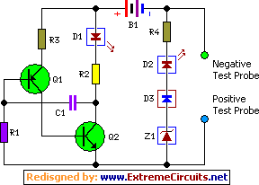
R1 = 5.6M
R2 = 1.8R
R3 = 15R
R4 = 220R
Q1 = BC327
Q2 = BC337
D1 = Green LED
D2 = Red LED
D3 = 1N4148
Z1 = 6.8V Zener
C1 = 0.033uF
B1 = 3V Battery