Home » Circuits
IC Controlled Emergency Light With Charger Circuit
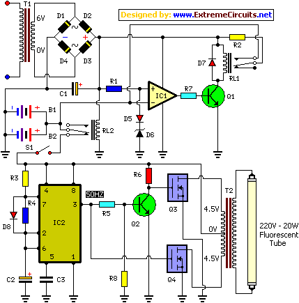
Here is the circuit diagram of IC Controlled Emergancy Light With Charger or simply 12V to 220V AC inverter circuit. The circuit shown here is that of the IC controlled emergency light. Its main features are: automatic switching-on of the light on mains failure and battery charger with over-charge protection. When mains is absent, relay RL2 is in de-energized state, feeding battery supply to inverter section via its N/C contacts and switch S1.The inverter section comprises IC2 (NE555) which is used in stable mode to produce sharp pulses at the rate of 50 Hz for driving the MOSFETs. The output of IC2 is fed to gate of MOSFET (Q4) directly while it is applied to MOSFET (Q3) gate after inversion by transistor Q2. Thus the power amplifier built around MOSFETs Q3 and Q4 functions in push-pull mode. The output across secondary of transformer T2 can easily drive a 230-volt, 20-watt fluorescent tube. In case light is not required to be on during mains failure, simply flip switch S1 to off position. Battery overcharge preventer circuit is built around IC1 (LM308).
Its non-inverting pin is held at a reference voltage of approximately 6.9 volts which is obtained using diode D5 (1N4148) and 6.2-volt zener D6. The inverting pin of IC1 is connected to the positive terminal of battery. Thus when mains supply is present, IC1 comparator output is high, unless battery voltage exceeds 6.9 volts. So transistor Q1 is normally forward biased, which energises relay RL1. In this state the battery remains on charge via N/O contacts of relay RL1 and current limiting resistor R2. When battery voltage exceeds 6.9 volts (overcharged condition), IC1 output goes low and relay RL1 gets de-energised, and thus stops further charging of battery. MOSFETs Q and Q4 may be mounted on suitable heat sinks.
Circuit diagram:

Parts:
Resistors
R1 = 1K
R2 = 10R-1W
R3 = 820R
R4 = 1K
R5 = 10K
R6 = 1K
R7 = 100R
R8 = 1K
Capacitors
C1 = 1000uF-25V
C2 = 10uF-16V
C3 = 0.01uF
Diodes
D1 = 1N4007
D2 = 1N4007
D3 = 1N4007
D4 = 1N4007
D5 = 1N4148
D6 = 6.2V Zener
D7 = 1N4007
D8 = 1N4148
Transistors
Q1 = SL100
Q2 = 2N2222
Q3 = IRF840
Q4 = IRF840
Integrated Circuits
IC1 = LM308
IC2 = NE555
Miscellaneous
S1 = SPST Switch
B1 = 6V-4A Battery
B2 = 6V-4A Battery
TI = 220V AC Primary to 0V-6V 250mA Secondary Transformer
T2 = 4.5V-0V-4.5V 5A Primary To 230V AC Secondary Transformer