Home » Circuits
Live Line Detector-Indicator
Detects the presence of a live mains conductor, Minimum parts counting
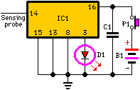
If the unit is brought close to a live conductor (insulated, and even buried in plaster) capacitive coupling between the live conductor and the probe clocks the counter, and causes the LED to flash 5 times per second, because the 4017 IC divides the mains 50Hz frequency by 10. When remote from a live line, the unit stops counting, the LED resulting permanently off.
Circuit diagram:
Parts:
P1 = SPST Pushbutton
D1 = Red LED (any type)
C1 = 100nF 63V Polyester or Ceramic Capacitor
B1 = 3V Battery (two 1.5V AA or AAA cells in series etc.)
IC1 = 4017 Decade counter with 10 decoded outputs IC
Sensing probe 3 to 15 cm. long, stiff insulated piece of wire
Notes:
- Sensitivity can be varied using a more or less long sensing probe.
- Due to 3V operation, the LED's current limiting resistor can be omitted.

