Home » Circuits
Motor Bike Headlight Controller Circuit
This circuit automatically turns a motor cycle's headlight on and off, independently of both the light and ignition switches, provided the battery is fully charged. The first stage uses the 22O resistor and ZD1 to hold transistor Q1 off while the motor is not running; it draws about 2mA. Once the battery voltage exceeds 7.0V during charging, Q1 begins to turn on.
The last stage uses the 22O resistor and ZD2 to turn on transistor Q2, which pulls the base of Q1 down, switching it hard on. In conjunction with the Vbe drop of Q2, ZD2 will turn off Q2 at a battery voltage of about 6.7V. In practice, this means that the headlight will be on most of the time while the motor is running and charging the battery. Heatsinks are required for both transistors. The circuit can be mounted adjacent to the battery with a single lead going to the headlight power feed.
Circuit diagram:
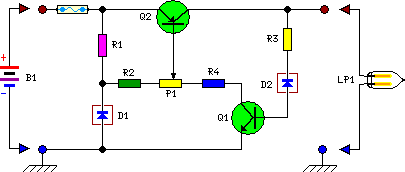
P1 = 5R - 3W
R1 = 220R -1W
R2 = 1R - 1W
R3 = 22R - 5W
R4 = 22R - 5W
Q1 = BD139
Q2 = MJ4502
D1 = 6.2V - 1WZener
D2 = 6.2V - 1WZener
B1 = 6.6V - 7.2V
F1 = Fuse 15A
LP1 = DIP Beam 6V-25W Halogen