Home » Circuits
Simple Capacitive Touch Sensor
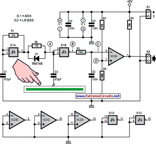
Capacitive touch sensors are based on the electrical capacitance of the human body. When, for example, a finger comes close to the sensor, it creates a capacitance to Earth with a value of 30 to 100 pF. This effect can be used for proximity detection and touch-controlled switching. Capacitive switches have clear advantages compared to other types of touch switches (for example 50 Hz or 60 Hz detection or resistance detection), but are often more complex to implement.Manufacturers such as Microchip have in the past designed specialist ICs for this purpose. However, it is still possible to design a reliable capacitive detector and/or switch using only a limited number of standard components. In this design we detect the change in the pulsewidth of the signal when the contact is touched. In Figure 1 the following stages can be recognised, from left to right:- a square-wave generator with a frequency of 300 kHz, using a Schmitt trigger IC (CD4093); - an RC network with a fly-back diode, followed by a Schmitt trigger/contact plate with an isolation capacitor of 470 pF; - an RC network that converts the change in pulsewidth into a voltage.
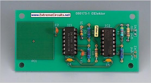
Picture of the project:
This voltage is about 2.9-3.2 V when the plate is touched (and 2.6 V when it isn’t touched); - an LM339 comparator is used to compare the voltage at point C with a reference voltage (D). The latter is set to about 2.8 V using a potential divider. As long as the contact plate is touched the output of the circuit will be active. To make the operation of the circuit clearer we have shown the signals at various points in Figure 2. The dotted line represents the signal when the plate is touched, the solid line when it isn’t touched.
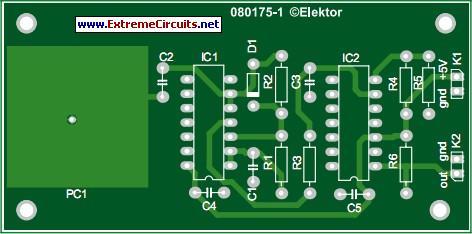
PCB layout:
The reference voltage at D has to be set up once via potential divider R4/R5 (change the value of R4). The required value is strongly dependent on the surface area of the contact plate (this is usually a few square centimeters). Larger surfaces increase the capacitance and the voltage at C will therefore be greater when the plate isn’t touched. The reference voltage at D should then be set closer to 3.4 V. The touch sensor can therefore also be made to work with larger areas (such as the complete metal enclosure of a device).
Circuit diagram:
The circuit only works when a connection for higher frequencies (300 kHz) is made to Earth in some way. The circuit therefore doesn’t work in battery-powered systems without a connection to Earth. In many systems without a direct connection to Earth there is sufficient parasitic capacitance to the mains Earth. In some cases it will be necessary to add an extra capacitor between the mains Earth and the Ground of the circuit. To comply with safety regulations this capacitor should be rated for>3-4 kV (i.e. a Class Y capacitor). The output signal can be used in various ways to switch on systems. The addition of an extra Schmitt trigger to the output is recommended in many cases, especially if the output connects to a digital input.
COMPONENTS LIST
Resistors
R1,R2,R6 = 10kO
R3,R5 = 100kO
R4 = 47kO
Capacitors
C1,C2 = 470pF
C3,C4,C5 = 100nF
Semicondcutors
D1 = 1N4148
IC1 = 4093
IC2 = LM339D
Miscellaneous
K1,K2 = 2-way pinheader
Downloads
The layout for the printed circuit board is available from the Elektor Electronics website as a free download; ref. 080175-1.zip.
Wim Abuys
Elektor Electronics 2008
Elektor Electronics 2008


