Home » Circuits
Water Level Alert
Beeper or flashing LED alert, 1.5V battery powered portable unit
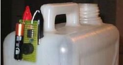
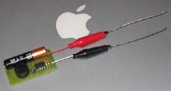
This circuit will emit an intermittent beep (or will flash a LED) when the water contained into a recipient has reached the desired level. It should be mounted on top of the recipient (e.g. a plastic tank) by means of two crocodile clips, acting also as probes. If a deeper sensing level is needed, the clips can be extended by means of two pieces of stiff wire (see pictures).
Circuit operation:
IC1, a 555 CMos timer chip, is wired as an astable multivibrator whose operating frequency is set by C1, R1 and R2, plus the resistance presented by water across the probes. If the resistance across the probes is zero (i.e. probes shorted), the output frequency will be about 3Hz and the sounder will beep (or the LED will flash) about three times per second. As water usually presents a certain amount of resistance, the actual oscillation frequency will be lower: less than one beep/flash per second. As probes will be increasingly immersed in water, the resistance across them will decrease and the oscillation frequency of IC1 will increase.
This means that a rough aural or visual indication of the level reached by water will be available. If a LED is chosen as the alert, C2, D1 and D2 must be added to the circuit in order to double the output voltage, thus allowing proper LED operation (see the rightmost part of the schematics). Interesting features of this circuit are 1.5V supply and ultra-low current consumption: 40µA in stand-by and 0.5mA in operation. This allows a single AAA alkaline cell to last several years and the saving of the power on/off switch.
Pictures of the project:
Circuit diagram:
Parts:
R1 = 1K - 1/4W Resistor
R2 = 100K - 1/4W Resistor (See Notes)
C1 = 2.2uF-50V Electrolytic Capacitor
C2 = 220µF - 25V Electrolytic Capacitor (See Notes)
D1 = 5 or 10mm. Ultra-bright red LED (See Notes)
D2 = 1N5819 - 40V 1A Schottky-barrier Diode (See Notes)
IC = 7555 or TS555CN CMos Timer IC
BZ = Piezo sounder (incorporating 3KHz oscillator)
B1 = 1.5V Battery (AAA or AA cell etc.)
Two small crocodile clips
Two pieces of stiff wire of suitable length
Battery socket, etc.
Notes:
- If a LED alert is needed instead of the beeper, R2 value must be changed to 10K, the Piezo sounder can be omitted and D1, D2 and C2 must be added, as shown in the rightmost part of the schematics.
- A common red LED can be used for D1, but ultra-bright types are preferred.
- Any Schottky-barrier type diode can be used in place of the 1N5819, e.g. the BAT46, rated @ 100V 150mA.
- Wipe the probes regularly to avoid excessive resistance variations due to partial oxidization.