Home » Circuits
Whistle Responder Schematic - Circuit Diagram
Beeps when hears your whistle, A gadget suitable for key-holders, games etc.
Some 20 years ago it was common to see small key-holders emitting an intermittent beep for a couple of seconds after its owner whistled. These devices contained a special purpose IC and therefore were not suited to home construction. The present circuit is designed around a general purpose hex-inverter CMos IC and, using miniature components and button clock-type batteries can be enclosed in a matchbox. It is primarily a gadget, but everyone will be able to find suitable applications.
Circuit operation:
This device beeps intermittently for about two seconds when a person in a range of around 10 meters emits a whistle. The first two inverters contained in IC1 are used as audio amplifiers. IC1A amplifies consistently the signal picked-up by the small electret-microphone and IC1B acts as a band-pass filter, its frequency being centered at about 1.8KHz. The filter is required in order to select a specific frequency, the whistle's one, stopping other frequencies that would cause undesired beeper operation. IC1C is wired as a Schmitt trigger, squaring the incoming audio signal. IC1D is a 2 second-delay monostable driving the astable formed by IC1E & IC1F. This oscillator generates a 3 to 5Hz square wave feeding Q1 and BZ1, thus providing intermittent beeper operation.
Circuit diagram:
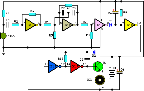
Parts:
R1 = 22K 1/4W Resistor
R2 = 10K 1/4W Resistor
R3 = 4M7 1/4W Resistor
R4 = 100K 1/4W Resistors
R5 = 220R 1/4W Resistor
R6 = 330K 1/4W Resistor
R7 = 47K 1/4W Resistor
R8 = 100K 1/4W Resistors
R9 = 2M2 1/4W Resistor
R10 = 1M5 1/4W Resistor
C1 = 47nF 63V Polyester or Ceramic Capacitors
C2 = 10nF 63V Polyester Capacitors
C3 = 10nF 63V Polyester Capacitors
C4 = 1µF 63V Electrolytic Capacitors
C6 = 1µF 63V Electrolytic Capacitors
C5 = 47nF 63V Polyester or Ceramic Capacitors
D1 = 1N4148 75V 150mA Diodes
D2 = 1N4148 75V 150mA Diodes
Q1 = BC337 45V 800mA NPN Transistor
B1 = 2.8 or 3V Battery (see notes)
IC1 = 4049 Hex Inverter IC
BZ1 = Piezo sounder (incorporating 3KHz oscillator)
MIC1 = Miniature electret microphone
Notes:
- Power supply range: 2.6 to 3.6 Volts.
- Standing current: 150µA.
- Depending on dimensions of your box, you can choose from a wide variety of battery types:
- 2 x 1.5 V batteries type: AA, AAA, AAAA, button clock-type, photo-camera type & others.
- 2 x 1.4 V mercury batteries, button clock-type.
- 1 x 3 V or 1 x 3.6 V Lithium cells.